LTSpice vs PSPICE (orCAD)

Thread Starter

PsySc0rpi0n

Joined Mar 4, 2014
1,755
Hello guys.

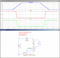
I have a schematic (already built by someone) ready-to-use to analyse it's output wave forms and I was trying to replicate it in LTSpice. But wave forms on LTSpice are way far from what PSPICE is showing up.

I'll attach files of LTSpice and screens of PSPICE. If anything else is needed, please ask!
pspice_psdiode_plot.png pspice_psdiode.png

I'm just not sure how to add 'series resistance' to the Voltage Controlled Switch! Not sure if it's important, or not!
 

Attachments

Last edited:

Thread Starter

PsySc0rpi0n

Joined Mar 4, 2014
1,755
AAC doesn't allow files not zipped but images!

Well, I'm not getting nice results from any of the circuits, so I'll post only LTSpice schematic screenshot. PSpice screenshots are alreay in my previous post.
LTSpice_psdiode.png


Edited;
@Jony130 I only saw your post now! Going to change!
 

Thread Starter

PsySc0rpi0n

Joined Mar 4, 2014
1,755
I can add here PSice diode parameters used...
upload_2017-11-1_19-2-42.png

The line that is not completely visible is:
Code:
d^@refdes %A, %K, mod^@refdes \n.model mod^@refdes d (rs=@rs)
 

Thread Starter

PsySc0rpi0n

Joined Mar 4, 2014
1,755
Ok...
I'm using also Yahoo Groups for this because there is a very well know LTSpice Group that has a lot of very experienced LTSpice users, such has this Ms Helmut Sennewald. He just picked up my PSpice Net List file of the circuit in question and turned it into an LTSpice usabe file. The plots are quite similar. I just couldn't understand the description he did about the changes he made. I'll let them here properly quoted and 'credited'.

From Yahoo LTSpice Group

Helmut Sennewald said:
Hello,

top-level netlist "PSDIODE_custom.cir" copied to "PSDIODE_custom_ltspice.cir" just work on acopy.

I changed .tran
I commented ".lib nom.lib" (If you need models from it, copy it into the folder of this netlist.)
I commented ".INC "PSDIODE_custom.als" (LTspice doesn't understand these aliases for the plot)
See the final top-level netlist below.

No changes done in "PSDIODE_custom.net" in this case.
Please note that the switch model VSWITCH has been used. It's different from SW. That's why I have to use VSWITCH in the schematic.
.model SW VSWITCH(Ron=1m)
and the didoe model is not a MUR460.
.model DD D(Rs=1m)
Last but not least there is an ".option gmin=1u" in the PSPICE netlist.
When I do all these changes in the LTspice schematic, the result has been the same.
See my files Diode-PSPICE-LTspice.zip and PS-net-LTspice-schem.GIF.
https://groups.yahoo.com/neo/groups/LTspice/files/ Temp/


Final contents of PSDIODE_custom_ltspice.cir

** Analysis setup **
*.tran 1n 60ns 0 0.1n SKIPBP
.tran 0 60n 0 0.1n
.OPTIONS GMIN=1u

* From [PSPICE NETLIST] section of pspiceev.ini:
*.lib "nom.lib"

.INC "PSDIODE_custom.net"
*.INC "PSDIODE_custom.als"

.probe
.END

Best regards,
Helmut

I'll upload a zipped file containing all Ms Helmut work... It has 2 folders, one with LTSpice stuff and another with PSpice stuff.

PS-net-LTspice-schem.GIF
 

Attachments

Thread Starter

PsySc0rpi0n

Joined Mar 4, 2014
1,755
It is your circuit, but with the switch model corrected :rolleyes:
Yeah, I know! I didn't remember that the SW model should be changed to be a little bit more realistic! I thought that with the changes you made I would probably get more visible results and closer to what PSpice was plotting out!
 

Thread Starter

PsySc0rpi0n

Joined Mar 4, 2014
1,755
Hello again...

In the circuit I posted above, how can I justify the voltage across the inductor of about 16V and also the voltage across the diode of 5V? I cannot understand these 2 values!

Thanks
Psy

Edited;
And also why there is no voltage reading across the inductor except for the moments when the controlled switch is activated/deactivated!
 

Jony130

Joined Feb 17, 2009
5,487
If my memory serves me well the voltage across the incudtor look like this:

VL = L* dI/dt

This equation indicates that inductance voltage depends not on current which actually flows through the inductance, but on its rate of change. This means that to produce the voltage across an inductance, the applied current must change. If the current is kept constant, no voltage will be induced, no matter how large the current. Conversely, if it is found that the voltage across an inductance is zero this means that the current must be constant but not necessary zero.

65.png

In summary:
When the current is increasing di/dt > 0, so V must be positive because L times a positive number yields a positive voltage.
When the current is decreasing di/dt < 0, so V must be negative because L times a negative number yields a negative voltage.
When we have no change in current over time then we cant have any voltage V = L*di/dt = L * 0 = 0.

As for the diode voltage 5V ?? when?


Top