I simulated the transformer using ltspice but couldn't figure out why don't the power value calculated with Vrms and Irms values match with the power value calculated by ltspice. Thank you for your time.
Thank you for the response, Eric. I found 56.36 mA using the rms values of the waveforms. Ltspice calculates average power as 30.3 mW. Theory states that Irms should be 17.1 mA (in case of no power loss), however, it is seen as 32 mA in ltspice.
Using the rms values of waveform I and waveform V from the first ss that I uploaded, the power generated by the primary circuit is 1.75 V * 32.115 mA = 56.36 mW. I mistakenly wrote it as 56.36 mA above; sorry for that.
Using the rms values of waveform I and waveform V from the first ss that I uploaded, the power generated by the primary circuit is 1.75 V * 32.115 mA = 56.36 mW. I mistakenly wrote it as 56.36 mA above; sorry for that.
You might want to repeat that calculation over an interval where both waveforms are in a steady state. the contribution from the transient part of the waveform may be skewing your results. You can do this by rerunning the simulation, but don't start collecting data until steady state has been reached.
You might want to repeat that calculation over an interval where both waveforms are in a steady state. the contribution from the transient part of the waveform may be skewing your results. You can do this by rerunning the simulation, but don't start collecting data until steady state has been reached.
Thank you for the response. I took some data by increasing stop time, changing relative response values, and solver. However, the current passing through the primary circuit is almost the same which is approximately 32mA.
The rms of current passing through the primary circuit is still around 32mA here, which yields the same result (56 mW) as I calculated before. Am I missing something?
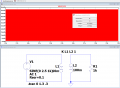
The time difference between the wave crests is around 0.163ms. The frequency of our source is 1kHz, so the phase difference is 0.163ms * 2π / 1ms ≅ 1.023rad. Vrms*Irms*cos(1.023) ≅ 30 mW.
 Facebook
 Google
 GitHub
 Linkedin