ltspice switch mode volt reg

Thread Starter

Random3s

Joined Jul 30, 2014
38
Hi all,

I am trying to design a SMPS using ltspice, this is part of a course I am currently doing.

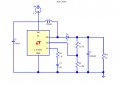
I have attempted to build a switch mode voltage regulator using an LT1070, with component values taken from a course textbook, attached is my circuit in LTspice.

I am not sure how to represent a load in ltspice. The output should be 12v 1A (5v input), but I am not getting this and I suspect its because of the values of load resistors I have used.

In the diagram I have represented the load with R4, 1k....

Id appreciate any pointers to set me on the right track here..
 

Attachments

Thread Starter

Random3s

Joined Jul 30, 2014
38
:D

I should have mentioned that by adding a 12 ohm resistor, the circuit failed to function correctly. Theres something missing or incorrect from the circuit.... I originally thought it was the choice of load resistance. ltspice is new to me, is there anything else you can see which would stop the circuit responding correctly?
 

MikeML

Joined Oct 2, 2009
5,444
You copied Linear Technology's test fixture (recommended circuit) for the LT1070 incorrectly. All the component values are the same (except for the Shottky diode, which is critical), but the connections are not.

Use their simulation directive, too.
 
Last edited:

Thread Starter

Random3s

Joined Jul 30, 2014
38
You copied Linear Technology's test fixture (recommended circuit) for the LT1070 incorrectly. All the component values are the same (except for the Shottky diode, which is critical), but the connections are not.

Use their simulation directive, too.
Actually I copied the text book circuit..... who apparently copied the test fixture circuit incorrectly.

But good to know there is a test fixture for components.
 

MikeML

Joined Oct 2, 2009
5,444
Actually I copied the text book circuit..... who apparently copied the test fixture circuit incorrectly.

But good to know there is a test fixture for components.
All of the LTC IC parts they supply Spice models for are built into the LTSpice simulator. Each has a example test circuit. For example, your LT1070: Here is how you open its "test fixture":

Macro.gif

You first push into the LTC-supplied PowerProducts library. Then you select LT1070. Then you click on Open this macromodel's test fixture. The test circuit opens. Same thing for OpAmps, etc.
 

Aaron Hinton

Joined Aug 13, 2015
3
Hello,

I have been trying to find suitable values for R1 and R2 in the circuit you have been discussing above to get an output of 9V/1.5 A.

I'm really struggling. Can any one give me some help or guidance?

Thanks =)
 
check this file
R1 = 10kΩ ; R2 = 1.6kΩ
Hello Jony,

Thanks for your very prompt reply. Ive taken a look at the file you sent. It seems that the circuit is stabilizing at 9V but the Amps are still not 1.5A. Do you know what is needed to make the circuit 9V/ 1.5A?

Cheers =)
 
Top