Lowering the input frequency for a frequency doubler using a single 4069

Thread Starter

teliocide

Joined Sep 26, 2013
126
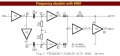
Its is claimed this circuit will operate over a wide frequency range.
However with the component values shown the width of pulses in E and F point is about 500ns, so the duty cycle of the output will be 50% when the frequency is 1MHZ, when the input frequency is 500KHZ.
This is far too high for my needs.
I need this circuit to operate at an input frequency of around 20Hz to 500Hz.

The component values will need to be changed for this lowered input frequency.
This is where my knowledge ends.
I need help with this.

Can some suggest the appropriate values please.
slow 4069.jpg
 

Attachments

crutschow

Joined Mar 14, 2008
34,281
That seems to be a rather complex circuit for frequency doubling.
But you should be able to get it to work at a lower frequency by increasing the value of capacitors C1 and C2.

Below is the LTspice simulation of a simple frequency-doubler circuit using one CD4070 XOR gate, one resistor, and one capacitor.

upload_2018-4-14_20-1-36.png
 
Last edited:

Thread Starter

teliocide

Joined Sep 26, 2013
126
Thanks,
Built it.
It works at 20Hz ,
I made a 555 SWO to test it at 20Hz.

I notice that the duty cycle is less than 50% in your graph..
How are the R and C values manipulated to match the desired frequency input range and the duty cycle?

Greg
 

crutschow

Joined Mar 14, 2008
34,281
The duty-cycle can only be made 50% for one frequency, as it's determined by the RC time-constant.

The RC value should be selected so that its signal at the XOR input has significantly decayed before the next input pulse, at the highest frequency of interest.
In the simulation I used a 600μs time-constant which is a little longer than the 500μs time between output pulses for a 500Hz input.
The shorter the time-constant, the shorter the output pulses from the XOR.

Here's the simulation showing the RC voltage:

upload_2018-4-15_0-47-39.png
 

Thread Starter

teliocide

Joined Sep 26, 2013
126
There is always disappointment lurking somewhere......

This circuit appeared to be operating perfectly ... and it was at 9VDC.
Further testing I raised the supply voltage to what might be expected as the maximum it would encounter under the conditions it will operated.
All was good until 12.5 volts, then the frequency began increasing significantly.
At 3.5v to 12.5v it outputs x2 the input. The source frequency was 19Hz and the output was 38Hz.
Above 12.5 volts to 15volts the frequency increased to 90Hz. The source frequency remained at 19 Hz at the same voltage.
A single common PS is used.
Where to now.?
BTW ....I have and LED in series with a 20k resister across U1 OUT and GND. Is this a problem?

Thanks for you help.
 

crutschow

Joined Mar 14, 2008
34,281
The LED and resistor should not have any effect.
Don't know what might be happening.
Can you post a picture of the input and output when it is malfunctioning?

Edit:
Above 12.5 volts to 15volts the frequency increased to 90Hz. The source frequency remained at 19 Hz at the same voltage.
What do you mean "the same voltage"?
The source signal voltage must be the same as the supply voltage for proper operation of the circuit.
 
Last edited:

Thread Starter

teliocide

Joined Sep 26, 2013
126
Thanks again,
"Can you post a picture of the input and output when it is malfunctioning?"
I imagine you mean from an oscilloscope ???? Don't Have, Sadly.

I will have to try to find a PC scope. I vaguely recall something called Z-scope.

"What do you mean "the same voltage"?"

Both the 555 signal generator and the CD4077BE frequency doubler run from a single variable power supply.
So while the CD4077BE frequency doubler was pumping 90Hz @ 15volts Vcc, the 555 signal generator was still at 19Hz @15Vcc.
Drop back to 9Vcc and the CD4077BE frequency doubler is outputting 38Hz, and the 555 signal generator was still at 19Hz.

Thanks
 

Thread Starter

teliocide

Joined Sep 26, 2013
126
Then I would suspect that may not be giving you a correct reading.
As a doubter of everything I checked this.
I connected the output from the CD4077BE frequency doubler to the input of an audio amplifier and separately also the 555 signal generator .
I can hear the difference between 19Hz and 38Hz and i can hear the increase in frequency as the Vcc rises above 12.5V.
So I have some confidence that the observation is real and not an artifact of a poor mans tools.
 

Thread Starter

teliocide

Joined Sep 26, 2013
126
Got PC CRO working ....... and some pics for you. Not sure why the source signal is not perfectly square.
I get the same shape whether I use my 555 or a PC.
30 nF as per your original circuit Appears to x2 frequency but duty cycle is almost nothing,
30nF.jpg

160nF
Better ...... but looks like it needs several 100 nF ...I also need to consider what happens when the source is raised to its max (200Hz)

160nF.jpg
 
Top