Low voltage going to switch

Thread Starter

ax1lla

Joined Apr 11, 2017
7
Hi,

I have an issue with the ceiling light in my laundry room. We had a florescent light and it went out. I got new bulbs and they didn't work. Swapped it out with LED light, and the lights would very briefly flicker when I flipped the switch but wouldn't turn on (not a dimmer). I changed this out with a regular light....and am still getting nothing. I changed the switch out....and still nothing.

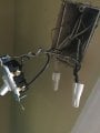
I checked the voltage to the switch and it is only reading 21.4. All my other outlets are reading at about 126.5. So, I assume there is an issue with the wires/power going to the switch.

Can you tell me what my next troubleshooting steps should be? I am a complete newb with electricity, but.....if there are additional troubleshooting steps I can do before calling an electrician.....I'd rather make the attempt first.


Thanks!

Corey
 

MaxHeadRoom

Joined Jul 18, 2013
28,702
Also depends how it is wired, if the feed is taken to the ceiling light and then spur down to the switch with a switch wire, a Screwit or Marrette connector in the ceiling fitting may have come loose.
Check connections in the light fixture box.
Max.
 

dl324

Joined Mar 30, 2015
16,943
Welcome to AAC!
Can you tell me what my next troubleshooting steps should be?
In general, you shouldn't be working with line voltage if you don't know what you're doing.

Where were you measuring the voltage to the switch?
Do you know which circuit breaker the light is on?
Do you know what other outlets and lights are on the same circuit? Are they showing the same symptoms?
 

Thread Starter

ax1lla

Joined Apr 11, 2017
7
There is not a separate fuse for the light. When I measured the voltage I set my digital meter to 200Vac and put it on each of the screws on the switch. On it was 0. Off it was only 21.4. i checked the other outlets in the house and verified I'm getting a normal value (126.5).

I have put in two ceiling lights (thinking it was that), so yes.....I know what circuit breaker its on (or I'd have had a nasty surprise - lol). I have firmly twisted the wires together and secured them with a wire connector and tape both times.

As far as other outlets on that circuit: I haven't mapped all of them. But, I can tell you that a few others i know to be on it....are fine.
 

MaxHeadRoom

Joined Jul 18, 2013
28,702
Re-read post #3, was the light fixture changed recently?
You said you swapped fluorescent for LED.
The switch usually picks up the live for the switch at the light fixture.
This is where it most likely the problem is.
Max.
 

ErnieM

Joined Apr 24, 2011
8,377
Yes,. But, how would that affect voltage going to the switch....?
It doesn't, it just keeps your meter from giving false readings.

AC power comes in on two wires, the hot and the neutral. Hot has the voltage while neutral is connected to ground somewhere so there is little voltage on it. It is actually safe to come in contact with this (just don't try this at home!).

If the neutral has a break your meter can read what we call a ghost from the connected hot wire to thin air. It's not really a voltage, but modern digital meters will display a stray voltage. Putting a bulb in the socket may short out this stray path... or not, depends on where that open is.

If your switch or light workbox has a ground (green or unshielded) try measuring to that. If you see the normal voltage you have an open neutral somewhere.
 
There is not a separate fuse for the light. When I measured the voltage I set my digital meter to 200Vac and put it on each of the screws on the switch. On it was 0. Off it was only 21.4. i checked the other outlets in the house and verified I'm getting a normal value (126.5).
This is what you don't understand. LED lamps would very likely give a meaningless number. An incandescent light would be "helpful". Why?

because with the switch off, the path is through the light bulb and it would return the neutral to the switch and you would get 120 V. When you close the switch there would be close to zero volts ACROSS the switch.

There are problems with this measurement. The 120 V that you measure might not be able to carry an appreciable current. The switch when attached to a load has a very small voltage drop. The contact resistance could be 0.010 ohms.

The LED lamp does all sorts of weird things.

Your location would possibly help when troubleshooting house electrical. 120 VAC may mean the US.

As was said, the power is likely in the ceiling fixture. The switch white wire should actually be taped black because the black wire is being switched. I forget which one is supposed to be connected to hot.

Ground is your friend here too because ground is eventually connected to neutral. If you measure from ground to each end of the switch, you should get 120 always and 120/0 depending on whether the switch is on or off. That's an important clue.
 

Thread Starter

ax1lla

Joined Apr 11, 2017
7
Thanks Ernie - can you specify how to measure to the ground? So, at the switch I put one lead on one of the screws....and the other on the ground wire somewhere? I've attached a pic of the inside of my switch btw.

mcgyvr - no dimmer or 3-way.
 

Attachments

Thread Starter

ax1lla

Joined Apr 11, 2017
7
Thanks for all the replies. Keep in mind I don't have an LED installed right now. It's just a regular incandescent fixture right now. I will try measuring from ground and report back.
 

ErnieM

Joined Apr 24, 2011
8,377
EXCELLENT PICTURE!!!

Here's what those wires mean:

Black wires (1,2,3) indicate a HOT wire. Some (one? #3?) of yours is switched thru the switch.

White wires (4) are the neutral, or the return for the power.

Unshielded (5) (or green) are the ground. Neutral is close in voltage to ground as they connect in your house, usually in the main breaker box.

Detail:

1: Hot incoming power. I see 3 wires twisted, so power in, power out, and power to switch.

2: Hot wire to your switch. Note wirees 1 and 2 should always have power.

3: Switched hot wire. This is the wire that goes up to your light fixture. Power controlled by this switch.

4: Neutral wire. Comes in from somewhere, goes two other places, one being the light fixture.

5: Ground wire, with no power.

You should read very little (< 1 VAC) between 4 and 5.

You should read the approximately 115 VAC between 1 and 4 or 1 and 5.

You should read the approximately 115 VAC between 2 and 4 or 2 and 5.

You should read the approximately 115 VAC between 3 and 4 or 3 and 5 when the switch is ON. Off read very little.

SWITCH.jpg
 

Tonyr1084

Joined Sep 24, 2015
7,905
Measuring between the three black wires under the wire nut, measuring to ground or to white should give you a 120 VAC reading. If not then you have issues further up the line back toward or to the breaker. If you have 120 VAC then you're off to a good start. Measure between one of the black wires on the switch and the white wires. If it's the black wire going to the wire nut you should read 120 VAC. If it's the black wire going up the sleeve on its own then with the switch in the ON position you should have 120 VAC. In the OFF - zero volts.

If that part is good then check for power at the ceiling, the black wires to the white wires. If no voltage is found there then measure black to ground. You should have voltage there (with the switch on). That would tell you that there is an open white connection somewhere. As for why you got the funny voltage readings before; refer to the drawing below. Measuring for voltage across a closed switch (ON) will give you zero volts. Measuring across an open switch (OFF) SHOULD give you 120 VAC. You're reading through the light bulb. If you're reading through an LED lamp - I couldn't tell you what to expect for voltage, I haven't the experience with that yet.

At the bottom of the drawing is a broken resistor - representing a blown bulb. You will get no voltage at all. You COULD get some residual capacitive voltage showing up but it's of no consequence. If you get a full 120 VAC and there is no bulb in the circuit then you have a short somewhere. But a circuit breaker would shut that down pretty quickly.

INTERRUPT VS MODERN.png
 

MaxHeadRoom

Joined Jul 18, 2013
28,702
Although electrically correct that does not really indicate the common wiring method in a physical sense.
Often a two conductor and GND is ran between light fixtures and a pair dropped down to the switch from the light point, one of the drop pair is connect to L1 the other becomes the switch wire.
Makes for simpler wiring.
Max.
 
Top