Facebook
 Google
 GitHub
 Linkedin
Related to: https://forum.allaboutcircuits.com/threads/looking-for-adc-for-cochlear-implant-signal.175340/ - yes, I'm still working on this.
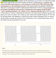
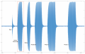
According to this section in the documentation 1), the 0 values should be "off" portions of the signal, but if you look at the wave as captured on a scope (displayed in octave), I don't see any breaks in the wave to suggest a 0 value. It's possible I'm capturing the wave incorrectly, though the packet examples in the documentation look equally filled with unbroken sine waves. Even if you were to rectify this wave, it looks like a series of unbroken, positive pulses. Can someone cure me of my ignorance?
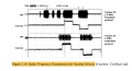
1) Cochlear implants: system design, integration, and ...National Institutes of Health (NIH) (.gov)https://pubmed.ncbi.nlm.nih.gov › ...
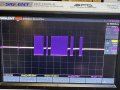
2) One captured packet, including sync, active electrode, mode, amplitude, phase 1, phase 2
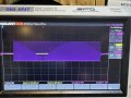
3) zoom-up of active electrode portion, showing series of waves
According to this section in the documentation 1), the 0 values should be "off" portions of the signal, but if you look at the wave as captured on a scope (displayed in octave), I don't see any breaks in the wave to suggest a 0 value. It's possible I'm capturing the wave incorrectly, though the packet examples in the documentation look equally filled with unbroken sine waves. Even if you were to rectify this wave, it looks like a series of unbroken, positive pulses. Can someone cure me of my ignorance?
1) Cochlear implants: system design, integration, and ...National Institutes of Health (NIH) (.gov)https://pubmed.ncbi.nlm.nih.gov › ...
2) One captured packet, including sync, active electrode, mode, amplitude, phase 1, phase 2
3) zoom-up of active electrode portion, showing series of waves
Attachments
-
 765 KB Views: 10
 -
 1.5 MB Views: 10
 -
 1.1 MB Views: 9