[LOGIC GATES] Constructing Ladders.

Thread Starter

darkmasta

Joined Oct 25, 2009
8
Hey guys I have a question that is confusing me.

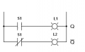
It is mentioned that the N.C -[/]- (normally closed) contact is similar to a Logical invertor (NOT).

How is a --|NOT|-- similar to a --[/]-- contact ?

Can someone please explain this with diagrams ?

Thank you very much !!

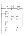
I am asking this because I want to know if this model is correct :

Son = On Switch
Soff= Off Switch
Lon = ON light
Loff= OFF light
M= Motor

The on switch should turn on the Motor and ON light. The off button should turn off the Motor and ON light, AND turn on the OFF light.
I have a mistake in the picture, the Soff should be N.C --[/]--


mik3

Joined Feb 4, 2008
4,843
A normally closed contact is a contact which conducts all the time. It stops condcuting when it is energized. It is the opposite of a normally open contact which conducts only when it is energized.
 

Jony130

Joined Feb 17, 2009
5,487
Look at this ladder diagram


We have on input switch S1 and two output lights.
When S1 is ON [1] then L1 [1] is ON ans L2 OFF [0]
And when S1 is OFF [0] then L2 is ON [1] and L1 is OFF [0].

And in your diagram you have two switch or only one switch?
And two lights ?
 

Attachments

Thread Starter

darkmasta

Joined Oct 25, 2009
8
Thank you all for replying. Mik3, yes I know that already, thanks for replying. Bertus I did check that page before posting this topic, thank you anyway :) .

Jony130 , thank you for explaining that :)
Yes I have two switches and two lights :

Son = On Switch
Soff= Off Switch
Lon = ON light
Loff= OFF light
M= Motor

Is my ladder diagram correct ? or is it wrong ?
 

Thread Starter

darkmasta

Joined Oct 25, 2009
8
I think it will be something like this
Thank you for replying !

Can you please explain the sketch ? does that mean there are more than 2 buttons ? there is an Son and Soff in the first rung, and the same in the second rung !

And does that mean my ladder model is incorrect ?

Thank you very much.
 
Last edited:

Thread Starter

darkmasta

Joined Oct 25, 2009
8
Thank you very much, really helpful :)

So your model is correct, right ? So I can assume mine is wrong. Can you tell me where is the mistake in my model ?
Thanks :)
 

JoeJester

Joined Apr 26, 2005
4,390
Using your first link ....

Rung 1 - Depressing the start button, and it is a momentary contact button, relay SI will energize IF the lube oil switch is energized, any of the three valves are closed, there are no alarms, and the motor overloads are not energized. The SI contacts in the Seal-in function forms a latch keeping the relay SI energized. When SI is energized, the Red lamp is energized and the green lamp is de-energized.

SI relay de-energizes when the momentary push button labeled stop is depressed, or the lube oil switch opens, or the alarm switch opens, or any motor overload switch opens, or all three valve switches open. The Red lamp will de-energize and the Green Lamp will energize.

My read is the relay contacts are drawn in the relay de-energized state. Of course I've seen diagrams where contacts were depicted in both states, thus making the diagram a little harder to read.
 
Top