Logarithmic amplifier

Thread Starter

chitofan

Joined Sep 30, 2012
15
Hi, can anybody tell me what kind of voltage error does a diode introduce into a logarithmic amplifier?

As far as i can guess, the diode can be modelled as a voltage source of 0.7v (usually) and would add on to the offset voltage, so there's your DC error?

I have found this to the best reference with regards to a basic diode-connected log amp (link), but we have not been taught to understand op amps on a transistor level so the meaning is not very clear to me. Any hints would be greatly appreciated.

Just to clarify, my homework assignment is to design an op amp through calculatation of the Vout error of an logarithmic amplifier. I'm not sure how the diode will have an impact on the omp amp output in the form of an error.
 

Attachments

Last edited:

bountyhunter

Joined Sep 7, 2009
2,512
Hi, can anybody tell me what kind of voltage error does a diode introduce into a logarithmic amplifier?

As far as i can guess, the diode can be modelled as a voltage source of 0.7v (usually) and would add on to the offset voltage, so there's your DC error?

I have found this to the best reference with regards to a basic diode-connected log amp (link), but we have not been taught to understand op amps on a transistor level so the meaning is not very clear to me. Any hints would be greatly appreciated.

Just to clarify, my homework assignment is to design an op amp through calculatation of the Vout error of an logarithmic amplifier. I'm not sure how the diode will have an impact on the omp amp output in the form of an error.
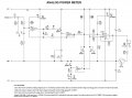
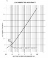
I actually designed and built a pretty accurate log amp to convert the audio input signal into log scale to show on a meter. The circuitry reveals a lot of where errors come from (see attached schematic). Also included is data from testing the log amp plotted on log paper to show it's accuracy.

Components U1-C up to Q2 are a peak detector so the signal applied to the log amp is basically DC or slowly changing AC, since log amps have very limited bandwidth. U1-D, Q1, Q3, and Q4 make a log amp. Q1, Q3, and Q4 are diodes (transistors wired as diodes) chosen for very close VBE values to minimize DC offset error to the following amplifier stage.

Since the output of U1-D goes through R11, it basically converts the input peak voltage into a current through Q3. The following stage amplifies the difference in voltage across the two diodes Q3 and Q4. Since the voltage change across a diode follows log scale as the current changes, this creates a log amp.

R18 on the following stage nulls out the DC offset.

The data curve shows the total accuracy from input all the way out to the meter.
 

Attachments

Last edited:

Thread Starter

chitofan

Joined Sep 30, 2012
15
Hi, thanks for the responses :) I'm not sure what to make of the info given because i haven't learned that much, and my problem involves a basic-diode log amp model.
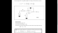
My homework assignment is basically just about DC imperfections so we can ignore other factors and so i focus purely on the impact of my choices for Rin, Rx and the chosen op amp parameters (Ib, Ios)

Here's my revised attempt at a solution

Using superposition theorem, we calculate the effects of Ib, Ios and Vos (RTI) separately and we get the total Vin/Rin (we need to express the error in terms of Iin) as
=
(Id + IB1 - ((IB2 * Rxx) / Rin)) (Ib effect)
+
(Id + (Ios/2)(1 + Rx/Rin)) (Ios effect)
+
(Id + Vos/Rin) (Vos effect)

Herein lies my dilemma, how am i going to work in these 3 Ids? So i turn to my lecturer's hint.

Since there is no value to substitute for Id in the error analysis, we calculate Vout in terms of Id (perfect and error values)

I derive the ideal op amp equation as Vout = -Vd = -25mV ln (Id/Is)
(Vt = 25mV)
Iperfect = Is * ln (Voutperfect/Vt)
Ierror = Is * ln (Vouterror/Vt)
Ierror/Iperfect = ln (Vouterror/Vt) / ln (Voutperfect/Vt)

This is the RTO gain, to convert it to RTI (for expressing error in terms of Iin) we divide it by the gain. But what is the gain when you have a diode in place of a resistor? Do we use the open loop gain, in which case i cannot find in an op amp datasheet (or at least i cannot find it)?

Now i am truly lost. Can someone give me some idea as to what is it that i have derived from algebra?
 

Attachments

Thread Starter

chitofan

Joined Sep 30, 2012
15
Then, how do you calculate the gain of a op amp with only 1 resistor? The general equation is (1+Rf/Ri) so how do you replace the Rf in place of a diode?
 

crutschow

Joined Mar 14, 2008
38,803
The diode equation replaces Rf. Thus the gain is [(diode eq)/Ri]. (The 1 in your equation is for a non-inverting amplifier, not an inverting amplifier that you show). The output voltage is thus a logarithmic function of the input voltage.
 

Thread Starter

chitofan

Joined Sep 30, 2012
15
I'm sorry if this is a dense question, but does that mean the gain is in amps (say, if i substituted 0.7v into Vd)? I understand 0.7v is a good measure of Vd for silicon diodes, but does the value change in an actual log amp?
 

MrChips

Joined Oct 2, 2009
35,176
Of course it does. That is why it is a log amplifier.
And that is why you cannot get accurate results because it depends on the reverse leakage current and it is also highly dependent on temperature.
 
The diode equation replaces Rf. Thus the gain is [(diode eq)/Ri]. (The 1 in your equation is for a non-inverting amplifier, not an inverting amplifier that you show). The output voltage is thus a logarithmic function of the input voltage.
Hi sorry to intrude,

If Vd is given to be 25mV*ln(Id/Is) and the diode is a generic with non specified Is.

Is there a optional/alternative to calculating gain? or is it even necessary?

As his objective should be to calculate for Vout_error to not exceed 10mV

On the side note what does fractional error=(Ierror/Iperfect) represents? Can I use Vin*fractional error to get Vout_error
 
Top