Facebook
 Google
 GitHub
 Linkedin
A little background:
After getting a good result with a custom fuzz pedal for my bass guitar, my friend asked if I could make a Boost pedal for him. Told him I'd try! I found a schematic for the "Alembic Stratoblaster" and built a version of it on protoboard (one I found called "Stratoblaster (Improved)" - not reposting because the image asks that it not be reposted on other sites (even though I found it on another site...)).
The boost worked, but the circuit was not useable due to noise. It's the first time I've experienced audible noise from the LM7809 voltage regulators that I've been using.
It's also the first time I've tried using a JFET (2N5458). Perhaps they are more susceptible to noise than other components I've used in the past?
So I did some research on circuits to reduce regulator noise and found this article:
https://www.edn.com/simple-circuits-reduce-regulator-noise-floor/
The article talks about the LM7805, but I reasoned that this should work for the LM7809 as well since they are in the same family.
I tried Figure 1 (capacitance multiplier) on a solderless breadboard and it seemed to work. So I went ahead and had a PCB made.
I just finished building it and hilariously it seems I've managed the opposite of what I wanted: it's amplifying the voltage regulator noise instead of filtering it... And so far I'm a little stumped to what I've done wrong.
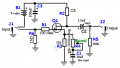
Here's my schematic. C1, C4 and C5 are all tantalum capacitors.

And here's my PCB outline in case I've done something wrong that I'm not aware of.

I'd appreciate any insights you may have - I'm still pretty new to making PCBs.
In the meantime I'm going back to protoboard to do some more experiments with the LM7809 and noise filtering.
Thanks for reading!
After getting a good result with a custom fuzz pedal for my bass guitar, my friend asked if I could make a Boost pedal for him. Told him I'd try! I found a schematic for the "Alembic Stratoblaster" and built a version of it on protoboard (one I found called "Stratoblaster (Improved)" - not reposting because the image asks that it not be reposted on other sites (even though I found it on another site...)).
The boost worked, but the circuit was not useable due to noise. It's the first time I've experienced audible noise from the LM7809 voltage regulators that I've been using.
It's also the first time I've tried using a JFET (2N5458). Perhaps they are more susceptible to noise than other components I've used in the past?
So I did some research on circuits to reduce regulator noise and found this article:
https://www.edn.com/simple-circuits-reduce-regulator-noise-floor/
The article talks about the LM7805, but I reasoned that this should work for the LM7809 as well since they are in the same family.
I tried Figure 1 (capacitance multiplier) on a solderless breadboard and it seemed to work. So I went ahead and had a PCB made.
I just finished building it and hilariously it seems I've managed the opposite of what I wanted: it's amplifying the voltage regulator noise instead of filtering it... And so far I'm a little stumped to what I've done wrong.
Here's my schematic. C1, C4 and C5 are all tantalum capacitors.
And here's my PCB outline in case I've done something wrong that I'm not aware of.
I'd appreciate any insights you may have - I'm still pretty new to making PCBs.
In the meantime I'm going back to protoboard to do some more experiments with the LM7809 and noise filtering.
Thanks for reading!
Last edited: