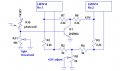
Well I have been using this gauge for awhile and now I would like to add adjustable led brightness using a photocell. Here is the circuit as it is now works great but is really bright at night.
Well I have been using this gauge for awhile and now I would like to add adjustable led brightness using a photocell. Here is the circuit as it is now works great but is really bright at night.
A day/night mode would be great, or variable could work but only down to a low limit ,the leds have to always be on at a visible level . Currently the output is about 19ma, but I think 18ma in the day and 10ma or 5ma for night, the thing is I think I will have to calibrate the night current in the field because I'm just not sure how dim I will want it to be.
This should give you manually adjustable nighttime brightness. It is a pulse width modulator (PWM) circuit which is only on during darkness. I know it probably has more parts than you would like. The conventional way to adjust brightness is to control the current out of the internal reference, but you have two of them, which complicates the issue. Also, if you do it that way, you could adjust the daytime brightness, but the dim setting would be fixed. I don't think that is the best way to do it.
I did some tests on the led light output if I had 19ma for day and 6ma for night that would just switch between to two millamps that would be good. I'm going to try to tie the two chips together in regards to the led current setting pins, do you think it would work?
I did some tests on the led light output if I had 19ma for day and 6ma for night that would just switch between to two millamps that would be good. I'm going to try to tie the two chips together in regards to the led current setting pins, do you think it would work?
No, that won't work. Those pins double as reference voltages. you can't tie them in parallel.
Do you still want to control the two settings with a photocell? If so, you still need a Schmitt trigger between the photocell and whatever you use to do the switching (e.g., transistor), so it won't be simple no matter how you do it.
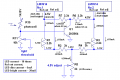
I see that R8 and R9 in your schematic get you very close to 4.5V nominal. If you want to use the somewhat simpler brightness control scheme that I have in mind, there are no 5% values that can get you close to 4.5V and also get the LED current you want. Furthermore, the internal reference has a ±5% tolerance. I think you need a pot to adjust the full scale voltage, unless you can tolerate as much as 10% error in it. Is that acceptable? If so, I think the circuit below will work. It should give you about 6mA dark current and 20mA daylight current.
It may be a few days before I get back to you, as I am going to be pretty busy (I'm going gold prospecting).
What about some 1% resistors ? If not I think a pot would be fine, I think 20ma is to high can we bring that down a couple ma ? My current circuit runs warm-hot with it set at 19ma.
What about some 1% resistors ? If not I think a pot would be fine, I think 20ma is to high can we bring that down a couple ma ? My current circuit runs warm-hot with it set at 19ma.
1% resistors will still leave you with a ±5% tolerance on the output, due to the specs of the LM3914. If that's OK, you can use 1%, but you will have to calculate the values yourself unless you can wait a few days.
Gold prospecting! In northern Nevada, with metal detectors, just for fun.
In the LM3914 application papers it says I need a unity gain buffer to control the led brightness on multiple chips if so how would I set this up and whats the math behind it?
I was also looking at the application papers for the LM3915 and LM3916, which if I understand them correctly are the same as a LM3914 except for the way the apply the comparators. If that is correct can I try to hook my LM3914s up something like the circuits on Page15,figure 12 in the LM3916 papers or page14, figure9 in the LM3915 papers ? If so can someone help explain the math I would like to understand how this all works.
In the LM3914 application papers it says I need a unity gain buffer to control the led brightness on multiple chips if so how would I set this up and whats the math behind it?
On the webpages you can download the pdfs. I also have the pdfs and I can post them here if I'm allowed to.I also mis-typed when I call them application notes they are the chips datasheets (sorry).
Ron H, I assembled the circuit you made up for me and it worked well. Can you please explain the math involved in making this circuit because I don't fully understand the series-parallel resistors and how the chips interact with the setup.
I know I have said it before but Thank You once again.
Bob
A unity gain buffer is also called a voltage follower. You can make one from an opamp by wiring the output to the inverting input, and connecting the signal to be buffered to the noninverting input. The output signal will closely track the noninverting input signal, with perhaps a small offset voltage added. An LF353 would be a good candidate for a voltage follower.
Ron H, I assembled the circuit you made up for me and it worked well. Can you please explain the math involved in making this circuit because I don't fully understand the series-parallel resistors and how the chips interact with the setup.
I know I have said it before but Thank You once again.
Bob
Sorry for taking so long to get back, I have been really busy. I have the circuit together and working well, I feel that I understand what is going on with the circuit (after much study ) I played with the display range and the day/night settings to make sure I understood the circuit and everything worked as expected.
I want to thank everyone who has helped me with this project, especially Ron H for all his help in the recent weeks.
 Facebook
 Google
 GitHub
 Linkedin