LM386_Amp test_Circuit

Thread Starter

CircuitHobbyist92

Joined Dec 2, 2024
8
Hello all,

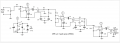
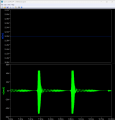
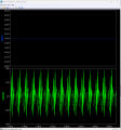
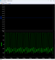
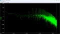
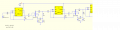
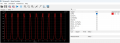
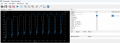
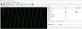
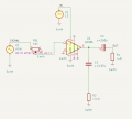
I'm new to electronics, trying to learn to build circuits. I want to simulate test LM386 circuit with default gain of 20db(taken from Texas Instruments LM386 official datasheet). I'm using Kicad as EDA environment. Since I couldn't find working LM386 spice model from online sources, I tried to build it myself using the internal schematics/circuit of LM386. But I don't get proper results on simulation in output - since signals look like noise without gain. I have attached both my Kicad Project along with LM386.lib(spice model) and simulation results.

Please help me to understand where I have made mistake and why simulation results are wrong/different than expected

Thanks,
 

Attachments

MisterBill2

Joined Jan 23, 2018
27,519
One thing stands out to me immediately is that none of the simulation needs to connect to earth ground. That connection does not do any good . And it may confuse the simulator. You can use a "common" connection tied to the 12 volt supply negative side.
The input signal is distorted both because it is excessive and also because it goes both above and below zero volts.
Also, you should have a feedback resistor between the output, pin 5 and the inverting input, pin 2. That can set the gain to a reasonable value. And the input voltage should be less, that is part of why the output is distorted.
 

MisterBill2

Joined Jan 23, 2018
27,519
That is the other method of setting the gain, and since the output looks a lot like extreme overdrive, is the reason I suggested reducing the gain. The pin#1 to pin #8 connections work for INCREASING the gain. The gain with pin #2 tied to common is about 20, by design.
The AC voltage shown is two volts peak to peak, and with a gain of 20 would give an output of 40 volts, which is not possible with a 12 volt supply. So distortion will happen, and lots of it, which is what is shown.

Certainly, with the LM386, gain reduction by negative feedback is not common at all. And in this case, with so great an input voltage, it may not work either.
The alternative option is to reduce the signal voltage, which had not been done in the example shown.
 

Thread Starter

CircuitHobbyist92

Joined Dec 2, 2024
8
That is the other method of setting the gain, and since the output looks a lot like extreme overdrive, is the reason I suggested reducing the gain. The pin#1 to pin #8 connections work for INCREASING the gain. The gain with pin #2 tied to common is about 20, by design.
The AC voltage shown is two volts peak to peak, and with a gain of 20 would give an output of 40 volts, which is not possible with a 12 volt supply. So distortion will happen, and lots of it, which is what is shown.

Certainly, with the LM386, gain reduction by negative feedback is not common at all. And in this case, with so great an input voltage, it may not work either.
The alternative option is to reduce the signal voltage, which had not been done in the example shown.
Thanks for valuable feedback. I knew that I overdrive the LM386. Later changed signal amplitude to much lower and still got distorted and not-even amplified output. Problem most probably lies on how I created SPICE model for internal circuitry of LM386. I didn't know about gain-reduction using negative feedback. That's interesting.
 

Thread Starter

CircuitHobbyist92

Joined Dec 2, 2024
8
There is RV1 in the final schematic but don't know if that was incorporated in the sim.
The problem is trying to duplicate the internal configuration of the LM386 without any data on the transistors.
You are correct. I found LM386 spice model from some source, but then later rebuilt it myself based on official internal diagram from datasheet. There I assumed generic NPN and PNP transistors. Most probably that's why it doesnt work as expected
 

Thread Starter

CircuitHobbyist92

Joined Dec 2, 2024
8
See. The electronic circuit contains Spice models.
View attachment 337523
Thanks a lot for sharing your working circuit. I downloaded Qorvo Qspice and used your schematic to simulate and it works as expected. I will switch to Qspice for now, to build my circuit. I just wanted to test basic LM386 amplification circuit, before building much complex circuit which is Neurophone circuit(Patrik Flanagan's device for transmitting sounds using nerves on the skin via ultrasonic piezo elements). I have attached full circuit diagram for Neurophone using 3 cascaded LM386 amplification stages. Can you please check what may be problem in this circuit or even if there is any issue?
 

Attachments

DickCappels

Joined Aug 21, 2008
10,661
It looks as though you are using the first two LM386's to boost gain. This is wasteful because you and obtain as much or more gain using something like and LM358 (dual op amp) in place of the first two stages, which is an actual op amp, while the LM386 is an audio amplifier (Application Specific Integrated Circuit) designed to deliver power and which needs the Zobel network to assure that it does not oscillate, thus costing you L1, C4, C5, and R11.

The first two amplifier stages can be a dual op amp set up as shown below (the reason I mention the LM358 is that it can work well with a single positive power supply.

1733743151814.png

This allows you to get rid of the interstage transformers and Zobel networks (which you probably don't need anyway).
 

Thread Starter

CircuitHobbyist92

Joined Dec 2, 2024
8
It looks as though you are using the first two LM386's to boost gain. This is wasteful because you and obtain as much or more gain using something like and LM358 (dual op amp) in place of the first two stages, which is an actual op amp, while the LM386 is an audio amplifier (Application Specific Integrated Circuit) designed to deliver power and which needs the Zobel network to assure that it does not oscillate, thus costing you L1, C4, C5, and R11.

The first two amplifier stages can be a dual op amp set up as shown below (the reason I mention the LM358 is that it can work well with a single positive power supply.

View attachment 337600

This allows you to get rid of the interstage transformers and Zobel networks (which you probably don't need anyway).
I was busy with other things, returned to building this circuit again. Thanks a lot for sharing alternative circuit that can do the same thing above. But I can't find TL081 spice model neither in Kicad nor in Qorvo Qspice. Building it from scratch will be error prone. Do you have working spice models for above TL081 chips(its variants TL082/83/84)? I would really appreciate that if you can share it
 

Thread Starter

CircuitHobbyist92

Joined Dec 2, 2024
8
All this can be calculated in Qspice. We just need more information about transformers. The inductance of the windings and the ratio of turns should be set (preferably the number of turns).
I have built above circuit in Qspice. It works as expected for 1Khz, but when frequencies above it like 5Khz, 10Khz and 15Khz it doesnt produce expected signal shape and it gots severely distorted. I thought it would be the same output for all audio frequencies? Why is it happening? What can I change in the circuit to achieve stability over wide frequency range? Also if you have working spice model for TL081 series chips(TL081/82/83/84), can you please share it as I can't find models online, neither can I generate realistic/accurate model due to missing. All I found is this: https://www.chegg.com/homework-help...-used-jfet-bipolar-opamp-made-numbe-q22759201 which is missing about types/models for JFET/Transistor/Diodes and Capacitor
 

Attachments

Thread Starter

CircuitHobbyist92

Joined Dec 2, 2024
8
hi C92,
This zip has the LTSpice LM386 modules etc.
E
Thanks. I have already LM386 spice model given to me by Bordodynov. I'm trying to build neurophone circuit based on this amplifier. Later Dick Cappels shared alternate circuit using TL081 op-amps. Maybe you have spice model for this op-amp? I would really appreciate if you can share it
 

Thread Starter

CircuitHobbyist92

Joined Dec 2, 2024
8
CircuitHobbyist92,
You just don't know how to use Spice programs.

View attachment 337917
I know how to use it and and I'm learning new things. What you shared is frequency spectrum of the output signal. I have built Neurophone circuit in Qspice and shared its outputs in time-domain with various input sine frequencies. As you can see output waveform shape is severely distorted when using 15Khz input signal, but in 1Khz its as expected - like what I want. My question is why its happening and how to prevent time-domain signal waveform shape distortion? What is causing it?
 

Attachments

Top