LM35 opamp LM358 relay temp CTRL´d for INCUBATOR

Thread Starter

ricky diaz

Joined Feb 16, 2015
71
I
remove R4, and make R1 a 100K, this will give you upto 2 volts on pin 3, also make the hysteresis resistor 500K, that should give you an hysteresis voltage of 7mV.
i´ve notice when the temp reach the set point the voltage drop in the pot once the low setting is reached the led comes up and the pot volt goes to inicial setpoint i guess that´s the hysteresis efect, never seen that before, interesting to me.
 

Thread Starter

ricky diaz

Joined Feb 16, 2015
71
DONE... i decided to step down as my power supply provide 5volts 1.5A, change R2 2.2K and no chattering in the relay now, no hot in the transistor so far, i will set everythin for a main test with 110v lamp on the relay main conector and run couple hours to check everythig before move to the veroboard, THAAAAAAAANKS a lot guys, let you know then for the final test.
 

wayneh

Joined Sep 9, 2010
18,127
The chatter may be due to insufficient wiring. Turning on the relay causes voltage to sag slightly and this disrupts the inputs to the op-amp. Try doubling the wires that carry current to and from the relay, and use dedicated wires for the rest of the circuit. Especially look at the ground wire return from the relay to Q1 to the power supply. Don't share a ground wire that also goes to the op-amp, run a separate ground for the ground wire for Q1.
 

Thread Starter

ricky diaz

Joined Feb 16, 2015
71
The chatter may be due to insufficient wiring. Turning on the relay causes voltage to sag slightly and this disrupts the inputs to the op-amp. Try doubling the wires that carry current to and from the relay, and use dedicated wires for the rest of the circuit. Especially look at the ground wire return from the relay to Q1 to the power supply. Don't share a ground wire that also goes to the op-amp, run a separate ground for the ground wire for Q1.
Very interesting Wayneh, that´s why enthusiast have to follow professionals, in fact i share some ground wiring in the proto so i´ll check that and try again i didn´t knew that, my board is very small need litle more space for next projects, for now no chatter since i down the power form 12v to 5v 1.4A, before move to final veroboard i´ll need fix all of this, thanks a lot for the advice man.
 

Dodgydave

Joined Jun 22, 2012
11,395
I personally think that the chatter is caused by the small hysteresis, you looking for an accuracy of 0.5 C, thats 5mV difference, i think it would be better using a triac and opto coupler.
 

wayneh

Joined Sep 9, 2010
18,127
I agree that small hysteresis could be the entire problem, although I have personally fought with the ground issues as well. Another issue I fought with was that the hysteresis of my final build was quite a bit different than on my breadboard. If I were the TS, I'd build with the expectation of needing to tweak the hysteresis of the final assembly. So leave room to add/remove a resistor, or use a 1MΩ trim-pot, etc.

Another way to help with hysteresis would be to amplify the LM35 voltage with the spare op-amp on the LM358. For instance suppose you need hysteresis to prevent chatter, but the hysteresis causes a 1C° deadband. A gain of 5 on the LM35 output would take the deadband down to 0.2C° while allowing the same degree of hysteresis at the comparator.

A downside of this approach is the upper temperature is limited. For example at 100°C, the LM35 is putting out 1V. A gain of 5 takes that to 5V . With a 5V power supply, that's out of useful range for the comparator. In a dedicated incubator application with a narrow range, this shouldn't be a problem.
 
Last edited:

Thread Starter

ricky diaz

Joined Feb 16, 2015
71
Ok so far what´s going on? 1) i change my power supply to 6.25Volts /350mA, Everything is working fine there, no chatter, no hot components, 2) Hysteresis is about 8 mV wich is ok for the range i need it last enough to turn off and on, 3) the amperage coming into the relay is about 2700uA (270mA?), the thing is the relay is a little hot, i´ve measured the coil and gives me 50 Ohms, so any advice on this will be wellcome, so far no chattering going on.
 

wayneh

Joined Sep 9, 2010
18,127
Good to hear most of it is working.

2,700µA is 2.7mA, which shouldn't heat up anything. But it shouldn't trip the relay either. Is this a 12V relay, which you are trying to operate with 5V?
 

Thread Starter

ricky diaz

Joined Feb 16, 2015
71
Good to hear most of it is working.

2,700µA is 2.7mA, which shouldn't heat up anything. But it shouldn't trip the relay either. Is this a 12V relay, which you are trying to operate with 5V?
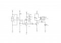
I´ts a 6v relay 50 Ohms coil, attached schemm shows everything.
tempsenrelay4.JPG
 

wayneh

Joined Sep 9, 2010
18,127
OK, thanks for the clarity. The coil should be drawing 6V/50Ω=0.12A or 120mA, and it is dissipating 6V•0.12A=7.2W. That's just like a C9 christmas bulb or a nightlight using on of those. Those do get warm, so it's not surprising the relay is warm when energized.

I'm not sure what you measured for current draw?
 

wayneh

Joined Sep 9, 2010
18,127
Uggh. I looked at that several times and thought it didn't look right. Should've listened to myself. Yes, 720mW. Warm but not hot.
 

Thread Starter

ricky diaz

Joined Feb 16, 2015
71
OK, thanks for the clarity. The coil should be drawing 6V/50Ω=0.12A or 120mA, and it is dissipating 6V•0.12A=7.2W. That's just like a C9 christmas bulb or a nightlight using on of those. Those do get warm, so it's not surprising the relay is warm when energized.

I'm not sure what you measured for current draw?
Yes datasheet say all that you wrote, probbaly i did measure in wrong way, anyway when i put the multimeter in serial for mA it show that in the screen in uA.
 

Thread Starter

ricky diaz

Joined Feb 16, 2015
71
Never mind guys, so far the temperature is normal in the range spec of the device i´ve measured and it shows 40 deg celsius outside the cover, anyway is a concern since this gona be probabbly inside de incubator i´ll try to think about it at the time.
 

Thread Starter

ricky diaz

Joined Feb 16, 2015
71
Finally i did measure in the right way the current draw by the relay and it take 2.9uA at 5.30Volts spec sheet say temperature is ok so far it goes over 50 deg celcius, in the circuit it shows 47 deg celcius so it is ok, well movin now to veroboard so far it is fine, let you know final test to share the circuit, thanks guys.
 

Thread Starter

ricky diaz

Joined Feb 16, 2015
71
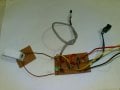
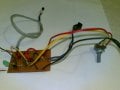
Finally here is the device ready, i just want to thank you all guys that guide me through the process specially Dodgydave and Wayneh i really apreciate your kindly attention, cheers.
Imagen005.jpg Imagen007.jpg Imagen008.jpgtempsenrelay4.JPG

 
Last edited:
Top