 Facebook
 Google
 GitHub
 Linkedin
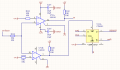
I'm trying to get a simple circuit working using an LM319. It's an oscillator which charges a capacitor with a current source, a comparator circuit monitors the output and switches the current source to discharge when the voltage meets a certain point (it's a little more complicated than that, but i'll leave the other details..)
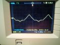
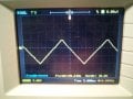
I did have my comparator set up and working but I changed it for the arrangement in the picture attached to get different trip points (I want +-5v). Although it sort of works (you have to wiggle the pots a bit to get an oscillation) the comparator isn't triggering in the right place - on the positive half it triggers at 5v as it should, but on the negative half it triggers at about -10v (attached picture shows asymmetric triangle wave). Looking at the inputs of the comparator, you can see there is a distortion on the negative portion of the signal (also pictured). Why is this happening? how can I fix the problem?
**I did have the +-5v lines connected to the inputs directly without the 10K resistors but it didn't work and i thought i may want something to avoid excess current, that's why they're there...
Attachments
-
 53.4 KB Views: 25
 -
 154.3 KB Views: 22
 -
 170.4 KB Views: 21


