LM317T, using it properly

Thread Starter

PeteHL

Joined Dec 17, 2014
475
Very good.
Should be cool. Only about 1 watt in the regulator.
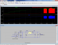
That's right, it SHOULD be cool. The problem is that when first turning it on, the drop-out voltage equals about 3V, which is according to design. But after ten minutes of operation the drop-out voltage has increased to more than 10V, and overheating of U1 ensues.
 

Thread Starter

PeteHL

Joined Dec 17, 2014
475
Ahh, It wants to oscillate. The power goes up then. Try a cap across the load and see how that works.
A cap across the load (20 uF, 470 uF, or 1000 uF) made no change to the increasing dropout voltage. Ditto for a 1000 uF cap connected from the output terminal of U1 to reference potential.

I was hopeful,
Pete
 

ian field

Joined Oct 27, 2012
6,536
Forgive me but how can you say the output voltage is 40 volts and it is a current regulator?

A current regulator varies its output voltage to hold the current constant.

So the output voltage will be whatever it needs to be to achieve the set current.
And so it will if you take the adj pin to the other end of a current sensing resistor in series with the output.

You can do the same thing with a 7805 - but the dissipation involved with dropping 5V on the current sensing resistor can be a bit much for some applications!
 

Thread Starter

PeteHL

Joined Dec 17, 2014
475
The problem with my circuit seems to be imminent failure of capacitors C1 thru C4 of the schematic in my post #19. Removing regulator U1 from the circuit and connecting the 80 Ohm dummy load to the unregulated power supply, the voltage across the dummy load was increasing with the operating duration, and then one of the 10 uF capacitors started to produce smoke.

So, for an application like this, probably electrolytic capacitors, even with a voltage rating of 450V are not suitable.

A capacitor such as a motor run capacitor is most likely what is required. If so, then this type of power supply is less advantageous, as motor run capacitors are fairly expensive and bulky.
 

ian field

Joined Oct 27, 2012
6,536
The problem with my circuit seems to be imminent failure of capacitors C1 thru C4 of the schematic in my post #19. Removing regulator U1 from the circuit and connecting the 80 Ohm dummy load to the unregulated power supply, the voltage across the dummy load was increasing with the operating duration, and then one of the 10 uF capacitors started to produce smoke.

So, for an application like this, probably electrolytic capacitors, even with a voltage rating of 450V are not suitable.

A capacitor such as a motor run capacitor is most likely what is required. If so, then this type of power supply is less advantageous, as motor run capacitors are fairly expensive and bulky.
As long as your capacitors are adequately rated for the circuit voltage, they shouldn't be under any stress in a simple linear regulator.

Three terminal regulators can, and sometimes do break into oscillation - this means a lot of ripple current dissipating energy in any ESR the capacitors may have.

Several manufacturers have published appnotes about this, with particular emphasis on the type and value of decoupling capacitors used close to the regulator.

Not sure where motor run capacitors got into this - but you might find it easier to obtain PFC capacitors for iron-ballast florescent fittings.
 

ronv

Joined Nov 12, 2008
3,770
The ripple current is pretty high in the caps - in the order of 1 amp RMS. I'm not sure why this would cause the voltage to rise, but I might guess yours are rated to low. Usually this type of circuit is used for small LEDs.
 

ian field

Joined Oct 27, 2012
6,536
also where are the bleeding resistors across capacitors between transformer and bridge rectifier?
In certain freak conditions, a bleed resistor on the rectifier/reservoir capacitor can destroy the regulator chip!

If the rectifier/reservoir capacitor discharges to 0V faster than the capacitor at the load end, current can flow backwards in the regulator and damage it.

Most people put a bypass diode from output to input, in normal operation where the regulator input voltage is higher than the output, the diode remains reverse biased - if for any reason the output voltage gets higher than the input, the diode conducts and limits the differential to 0.7V.
 

Thread Starter

PeteHL

Joined Dec 17, 2014
475
C1 thru C4 (the schematic of post # 19) are under a lot of stress, I would think. According to my reference, the ripple current rating of those capacitors "should be equal to the largest AC-line current, such as the the current with the load short-circuited." Never having even heard of a ripple current rating before, I sought electrolytic capacitors with the highest voltage rating that I could get within reason.

My reference suggests using motor-run or lighting ballast capacitors. My usual sources for parts don't offer lighting ballast capacitors.

Certainly not an expert on this, but possibly as the electrolyte of an electrolytic capacitor is boiling and evaporating, then short circuits in the capacitor might develop? If so, that might explain the increasing output voltage of the unregulated supply.

What I might investigate is 3 parallel strings of 4 LEDs each, or if necessary 4 parallel strings of 3 LEDs. That way the output voltage of the unregulated supply would be reduced by one-third or 0ne-fourth, and then capacitance of the voltage dividing capacitor would be substantially lessened. That might make it possible to use a (non-polar) polypropylene film capacitor(s). Current to each string of LEDs would be regulated by a LM317T. I paid 71 cents for a single LM317T, so that doesn't increase the cost that much.

The paper by Sokal and others, "Step-down rectifier makes a simple dc power supply" has been my design guideline for the unregulated power supply. See the link.

Regards,
Pete
www.hamill.co.uk/pdfs/sdrmasdp.pdf
 

ronv

Joined Nov 12, 2008
3,770
You have plenty of voltage to work with. Why not put more in series to get the current down. If you can post the case size of the caps we can guess the ripple current rating. But your right X10 caps would be safest.
 

Thread Starter

PeteHL

Joined Dec 17, 2014
475
You have plenty of voltage to work with. Why not put more in series to get the current down. If you can post the case size of the caps we can guess the ripple current rating. But your right X10 caps would be safest.
Do you mean increase the number of LEDs in-series? Doing that wouldn't decrease the current, as I want current thru all of the LEDs equal to 1/2A. But you are right, current thru the load is the stumbling block in trying to reduce capacitance of the voltage dividing capacitor.

The case sizes of the 22 uF & 10 uF caps are respectively 16 mm by 32 mm, and 13 mm by 25 mm.

What is a X10 cap?

Thanks,
Pete
 

Thread Starter

PeteHL

Joined Dec 17, 2014
475
The closest one to that size I found was only good for 135 ma. ripple, but there are others better, but probably not good enough unless you get snap ins or something like that.
Here is an example of AC caps that I mentioned.
Thanks for the spec. sheet on those AC caps; those look like maybe what I should be working with.
 

Thread Starter

PeteHL

Joined Dec 17, 2014
475
[QUOTE="ronv, post: 796210, member: 33234
Here is an example of AC caps that I mentioned.
http://www.mouser.com/ds/2/136/MKP_B32794_798_preliminary-76347.pdf
[/QUOTE]

The specification of ESR of the Epcos polypropylene film capacitors is at 10 kHz. In calculating ripple current, could I assume ESR as specified, or would there be a large change of ESR at 60 Hz? In the data sheets I didn't find any guidance on calculating ESR at 60 Hz. I'd rather not make my same mistake twice :).

At Mouser, only a few of the smaller and less expensive Epcos caps are available in quantities of a few :( . But the Epcos capacitors are still a lot smaller than a motor-run capacitor.

The polypropylene film capacitors with more capacitance must be a new development of the 21st century, as Sokal in his article ("Step-down Rectifier") of 1998 suggests electrolytic capacitors where capacitance must be greater than several microfarad.
 

Thread Starter

PeteHL

Joined Dec 17, 2014
475
The schematic of my step-down rectifier for lighting a string of 12 LEDs (rated 3W each), modified following the advice of ronv, is shown below. The modification involves replacing electrolytic capacitors C1-C4 and the associated diodes of the circuit shown at my post #19 with a metallized polypropylene film (MKP) capacitor.

Today I tried continuously operating the below circuit for 4 hours replacing the LEDs with a dummy 80 Ohm load. U1's dropout voltage was a steady 3V throughout the test (Yeah!)

It really does seem very likely that I now have a working light. Thanks again, ronv.

Regards, Pete
12LEDS~1.png
 

ronv

Joined Nov 12, 2008
3,770
Great! :D
Don't forget to add the bleeder resistors someone mentioned earlier so you don't zap yourself when you have it off.
 

ian field

Joined Oct 27, 2012
6,536
The schematic of my step-down rectifier for lighting a string of 12 LEDs (rated 3W each), modified following the advice of ronv, is shown below. The modification involves replacing electrolytic capacitors C1-C4 and the associated diodes of the circuit shown at my post #19 with a metallized polypropylene film (MKP) capacitor.

Today I tried continuously operating the below circuit for 4 hours replacing the LEDs with a dummy 80 Ohm load. U1's dropout voltage was a steady 3V throughout the test (Yeah!)

It really does seem very likely that I now have a working light. Thanks again, ronv.

Regards, Pete
View attachment 78399
You have 2 constant current arrangements in series - all the volt-drop will be imposed on whichever regulates at the lower current.
 

Thread Starter

PeteHL

Joined Dec 17, 2014
475
ronv- The step-down rectifier will be permanently installed in a plastic case, so I'm treating a bleeder resistor as unnecessary. If it were necessary, then that would also mean some additional loss of efficiency.

ian field- The equation that I used (from the paper by Sokal and others) in calculating capacitance of C1 determines the output voltage of the step-down rectifier taken at the DC voltage output of bridge rectifier D1. This is referring to the schematic in post #37. So I would say that first there is voltage step-down/ rectification followed by current regulation by U1 (LM317T). This is also the way the step-down rectifier is presented in the paper, as a means for obtaining a certain reduced DC output voltage.

If you are saying that the step-down rectifier portion of the circuit is actually a current regulator, can you explain?

Regards,
Pete
 
Top