 Facebook
 Google
 GitHub
 Linkedin
Hi Guys
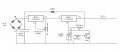
i found a LM317 variable current and voltage regulator
actually i need current from 100ma to 1.2 AMP with voltage between 13 to 14.5 volts
any help and development for this circuit please to be an industrial circuit !!
i really appreciate that
thank you
i found a LM317 variable current and voltage regulator
actually i need current from 100ma to 1.2 AMP with voltage between 13 to 14.5 volts
any help and development for this circuit please to be an industrial circuit !!
i really appreciate that
thank you
Attachments
-
 57.3 KB Views: 102
") but i'm not familiar with electronic at all
but i'm not familiar with electronic at all 


