 Facebook
 Google
 GitHub
 Linkedin
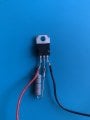
Im trying to make simple laser diode driver from this video
I do everything like on video but i dont get any output voltage on lm317t
(1-12v tested on power supply)
(1-12v tested on power supply)
Attachments
-
 1.1 MB Views: 24


