Facebook
 Google
 GitHub
 Linkedin
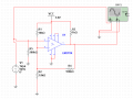
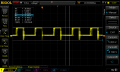
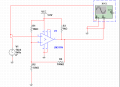
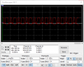
Ive breadboard this LM311 comparator circuit but it does not seem to behave correctly, or at least how the simulations behave in multisim.
Attachments
-
 16.4 KB Views: 17
 -
 22.8 KB Views: 15
| Thread starter | Similar threads | Forum | Replies | Date |
|---|---|---|---|---|
| M | Low fuel light with LM311N | General Electronics Chat | 5 | |
| C | LM311N comparator switching | General Electronics Chat | 6 | |
|
|
help needed with LM311N comparator | General Electronics Chat | 10 | |
|
|
help with LM311N Comparator | Homework Help | 2 | |
| B | LM311N comparator HELP please. | General Electronics Chat | 5 |