LM2907 Tachometer (TACH- pin) Help

Thread Starter

Swarly88

Joined Nov 12, 2018
25
Greetings,

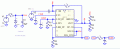
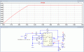
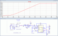
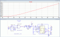
I am trying to utilize an LM2907 Tachometer (the 14 pin package) to convert the frequency of the rotation of an RC car wheel into a voltage, which will eventually be used for feedback reference for speed control using a PI controller. Anyways, an IR-encoder reads the interior of the wheel that has reflective and non-reflective tape sectioned into 8 sections, like a pizza. After reading the datasheet for the LM2907, I am having some confusion on the purpose of pin 11 on the 14-pin package. It is listed as TACH-, and is internally grounded on the 8-pin package. The description of the pin on the datasheet is the negative terminal of the input signal to the non-inverting terminal of the internal schmitt trigger. The input signal would be a 0-6V square wave (I have the encoder feed into a previous schmitt trigger to help clean up the signal and give a true high-low waveform). Would the 0V that could be fed into the input be fighting with this pin 11 TACH- as to which is technically the lower potential? Or would I need say a voltage divider to be attached to that pin to give it a slight bias?
 

Attachments

ericgibbs

Joined Jan 29, 2010
18,766
hi 88.
Its -Vin.
Look at the way its connected in his sim circuit.
E

Update:
If you post the final circuit I could run it in LTSpice simulation.
 

Attachments

Last edited:

Thread Starter

Swarly88

Joined Nov 12, 2018
25
That schematic looks like its attempting to bias pin 11 just a bit to make it not-zero? The datasheet indicates that when that pin is grounded, it attempts to slam the output to 0V. Which makes sense considering the op-amp involved. The input power to the IC is regulated from an LM317, by the way. Linearity has been the biggest issue so far.

And the values I am currently juggling are:

C1 = 0.1 uF
R1 = 70k ohm
C2 = 10 uF
R2 = 1k ohm

I am trying to get a 0 to 3.3V range on my tachometer output to coincide with a 3.3V reference that I am using from my microcontroller and a 10k turnpot.
 

ericgibbs

Joined Jan 29, 2010
18,766
hi,
Look at R2 and R3 they form a divider from the 14V supply, so the junction is at approx +0V

Post the circuit you have so far.
E

Voltage edited.!
Added a sim run, note the -Vin
 

Attachments

ericgibbs

Joined Jan 29, 2010
18,766
Here is my current setup. The input, by the way, is a 0-6V squarewave.

What is the input frequency range.?


Update:
This is your circuit with a 1kHz input, added some components, you need to recalc some values.
 

Attachments

Last edited:

Thread Starter

Swarly88

Joined Nov 12, 2018
25
Would those results have anything to do with me grounding pin 11? When hooked it directly to a function generator, as soon as I set the DC offset above 0 V, the output slams to 0V. Conversely, when even slightly below 0V, it allows for an output.

I can still adjust R/C to better fit my desired output. I believe my C1 should be fine as is because the data sheet indicates it should be higher than 500 pF.
 

eetech00

Joined Jun 8, 2013
3,859
Hello

The linearity will be affected by the size of C2 but the trade off for the size of C2 is between output ripple, response time and linearity. Its going to take some experimenting on your part to come up with the values. If you make C2 too large, response time suffers (however, ripple is reduced). The simulation below uses a 9v supply for the chip. Keeping the supply above 7.5 volts helps linearity. One version of this chip comes with an internal 7.5 Zener regulator.

See simulation below.

eT

1573517603515.png
 

Thread Starter

Swarly88

Joined Nov 12, 2018
25
Unfortunately, I won't be able to adjust the 5.5V Vcc for the tach because I have the encoder taking that in as its supply. Thank you for the insight everyone who has responded!
 

eetech00

Joined Jun 8, 2013
3,859
Any idea why that is the case? Just curious is all. Are there any subtlies to the LM2907 similar to that that can affect its operation.
Hi

I haven't found any notes regarding VCC vs linearity other than is should be stable for best accuracy. I guess I was really thinking minimum supply of 6v plus CM of 1.5v. :-| Upon reviewing the datasheet, I didn't see anything actually stating the minimum supply voltage but 6v seems to be the limit. What supply voltage did you want to use? There is also a CM input voltage of 1.5v to consider so you'll need to reduce the input signal at least that much below the supply voltage.

eT
 

Thread Starter

Swarly88

Joined Nov 12, 2018
25
I'll be forced to use a 5.5V input. I am regulating a 7.2V RC battery to power the various IC's I am using and that particular power rail on my breadboard will be the 5.5V line.

As far as the operation of the LM2907 itself, would the fact that the encoder I am using to feed its input signal be an issue? Specifically, it has an IR diode to read reflective tape on the interior of my vehicles wheels, which biases a transistor, and translate the speed at which it reads ON and OFF as frequency. My concern with this is that sometimes the wheels may naturally stop on a section of wheel that is reflective - or non-reflective, which would translate to light being reflected back into the diode, which would bias the accompanying transistor, which would output a voltage on the encoder. Granted, this voltage would be purely in a HIGH state, and not be changing. Would the LM2907 be able to discern that? Like does it only care if states on its input are changing, not if they are continuously HIGH or LOW?
 

ericgibbs

Joined Jan 29, 2010
18,766
hi,
The C3 01.uF on my Sim blocks a DC signal, so the steady reflection will not trigger the LM2907.
You should have the 0.1uF in the circuit.

E
 

eetech00

Joined Jun 8, 2013
3,859
I'll be forced to use a 5.5V input. I am regulating a 7.2V RC battery to power the various IC's I am using and that particular power rail on my breadboard will be the 5.5V line.

As far as the operation of the LM2907 itself, would the fact that the encoder I am using to feed its input signal be an issue? Specifically, it has an IR diode to read reflective tape on the interior of my vehicles wheels, which biases a transistor, and translate the speed at which it reads ON and OFF as frequency. My concern with this is that sometimes the wheels may naturally stop on a section of wheel that is reflective - or non-reflective, which would translate to light being reflected back into the diode, which would bias the accompanying transistor, which would output a voltage on the encoder. Granted, this voltage would be purely in a HIGH state, and not be changing. Would the LM2907 be able to discern that? Like does it only care if states on its input are changing, not if they are continuously HIGH or LOW?
If you use a 1uf cap at the input, as ericgibbs suggests, there should be no issue as it will block steady DC.
As far as the 2907, it only cares about pulse frequency....a steady DC input would read approx. 0dc output.

Its unclear from your comment if you have a 7.2v or 5.5v supply for the 2907(?)
You can divide down the input from the encoder to the 2907 if necessary.

BTW-I have the circuit on the bench as shown(9v supply), and it works as intended.

eT
 
Top