LM1117 .lib from TI imported to LTspice not working right?

WBahn

Joined Mar 31, 2012
33,074
Do you think I would see oscillation if I did not use the caps?
You probably won't see an impact on your simulation (for a schematic this simple), but in real life you want them there to reduce the ripple at the input, which greatly improves the regulation, and at the output to reduce the ripple caused by the load.
 

Thread Starter

jim0000

Joined Oct 28, 2020
130
Inside the model is a node that is specified as having an initial condition of 0 V. That may be causing you problems.

Set your V1 to be a PWL source that ramps from 0 V at t=0 to 15 V at t=15 s and then run a transient simulation for 15 seconds.
When I try to run for 15s I get a 'time step too small' error.

I am using PWL(0 0 15 15)
.tran 0 15
 

Papabravo

Joined Feb 24, 2006
22,105
1670304510512.png
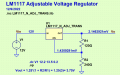
I would surmise that if you can't get the DC operating point correct there is not much hope for the model in its present form. I did modify the auto generated symbol to make it less crowded. I also used the resistor values for an output pf 3.75V. As you can see there is no happiness here.
 

WBahn

Joined Mar 31, 2012
33,074
Oh, wait a minute, your .tran statement is saying something weird. You don't tell it to start at t=0 since that's the only place for it to start. Try

.tran 15
 

Thread Starter

jim0000

Joined Oct 28, 2020
130
View attachment 282309
I would surmise that if you can't get the DC operating point correct there is not much hope for the model in its present form. I did modify the auto generated symbol to make it less crowded. I also used the resistor values for an output pf 3.75V. As you can see there is no happiness here.
Yeah it looks like the output didn't make it there, I could only get it to work using the .tran command
 

Thread Starter

jim0000

Joined Oct 28, 2020
130
Oh, wait a minute, your .tran statement is saying something weird. You don't tell it to start at t=0 since that's the only place for it to start. Try

.tran 15
Yeah I noticed that and switched it to get the result I got in my last reply. Still needed to start at 10V though as you said.
 

WBahn

Joined Mar 31, 2012
33,074
Try walking the PWL starting voltage down and see how close to 0 V you can get before it complains.

When you start a simulation, the simulator has to figure out what all of the initial voltages and currents are (this is the operating point calculation), which may or may not converge (this is often due to nodes that don't have a DC path to ground and also don't have an initial condition specified on them). Then it starts the simulation by assuming a time increment and calculating how much things change over that increment. If any of those changes are too big, it tries again with a smaller time increment. This continues until either all of the changes are small enough that it is happy calling the discrete-time simulation an acceptable model of a continuous-time system, or the time step gets so small that it is pointless to continue because the simulation would take forever to run.

But in this case, I think the time-step too small is related to the print-time interval being too small (namely zero).
 

Thread Starter

jim0000

Joined Oct 28, 2020
130
Try walking the PWL starting voltage down and see how close to 0 V you can get before it complains.

When you start a simulation, the simulator has to figure out what all of the initial voltages and currents are (this is the operating point calculation), which may or may not converge (this is often due to nodes that don't have a DC path to ground and also don't have an initial condition specified on them). Then it starts the simulation by assuming a time increment and calculating how much things change over that increment. If any of those changes are too big, it tries again with a smaller time increment. This continues until either all of the changes are small enough that it is happy calling the discrete-time simulation an acceptable model of a continuous-time system, or the time step gets so small that it is pointless to continue because the simulation would take forever to run.

But in this case, I think the time-step too small is related to the print-time interval being too small (namely zero).
It looks like it works as long as I start at 2V or above. At 1V I get the error. Thanks!
 

Papabravo

Joined Feb 24, 2006
22,105
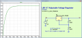
1670305495053.png
The PWL thing did not work at all, and the .op, and the .dc simulation have their problems; so, it seems we are kind of limping into an answer.
 

crutschow

Joined Mar 14, 2008
38,674
I also have the same odd problem in the simulation where the .dc step of V1 does not work with the LM1117 model.
It does work if I substitute the similar LM317 in the same circuit.

Using the Transient test with the V1 pulse source varying from 12.2V to13.5V with the LM1117 works, so it is apparently a model problem.
 

Papabravo

Joined Feb 24, 2006
22,105
I also have the same odd problem in the simulation where the .dc step of V1 does not work with the LM1117 model.
It does work if I substitute the similar LM317 in the same circuit.

Using the Transient test with the V1 pulse source varying from 12.2V to13.5V with the LM1117 works, so it is apparently a model problem.
It is hard to speculate on the root cause of the problem without taking a deep dive into the actual implementation details of the model. I would be curious to know if the model behaves differently in an actual pspice simulator. Spice is supposed to be spice, but we all know that is not always the case.

It turns out that the community is actually not very good at validating and supporting different models, since there is no central authority that performs this function. There are not even what might be called "best practices" when it comes to constructing models. There are different approaches and not much in the way information about the implementation choices made for a particular model.
 

WBahn

Joined Mar 31, 2012
33,074
I also have the same odd problem in the simulation where the .dc step of V1 does not work with the LM1117 model.
It does work if I substitute the similar LM317 in the same circuit.

Using the Transient test with the V1 pulse source varying from 12.2V to13.5V with the LM1117 works, so it is apparently a model problem.
As explained previously, the reason that the DC Analysis doesn't work in this case is because that analysis relies on the DC operating point calculation, which is the starting point of a transient simulation.

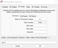
Look at the description of the DC sweep command in the LTSpice dialog:
1670350271042.png

If you look at the transient response, what is the DC operating point for this circuit? It's essentially 0 V. The circuit starts at 0 V and ramps up to the final output voltage after about a half a millisecond. So no matter what you set Vin to, the DC operating point is nearly identical at very close to 0 V. This is because the TI model includes behavioral modeling to simulate the start-up behavior of the device.

If you look at a transient response for your LM317 circuit, you will almost certainly find that at t=0 the output is already at the final output voltage, The same is true if you use the LT model for the LT1117.

So which model has a "problem"? The model that includes startup behavior, or the model that assumes that the device is able to power up and be stable instantly?
 
Top