Facebook
 Google
 GitHub
 Linkedin

Hi All,
For background, I am very, very new at learning electronics & semi conductors.
Today's pesky question concerns using transistors to gain higher output from an LM series regulator. I understand how the LM78 & 79 regulators operate (basically). I also have a basic understanding of transistors. But, i can not seem to understand how the LM78xx controls the voltage level allowed through the transistor, especially in the second example below.
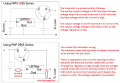
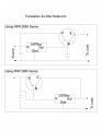
I have found two basic arrangements. A quick & rough sketch is attached to this post. For my examples, I'm using LM7805 & the source voltage is 18vdc.
One uses an NPN transistor with the base connected to the output of the LM7805 regulator. I think I understand this one-
Because the voltage on the output of the LM7805 is regulated to +5, the base of the transistor receives +5 volts. The input voltage of +18 at the emitter is allowed to flow out of the collector at only +5 volts due to the base receiving +5 (controlled by the LM7805's output terminal).
If the output were 12 volts from an LM7812, the base would receive +12 & the transistor would 'take in' +18 and send out +12.
Did I understand correctly or goof it all up?
The second method uses a PNP transistor. This is the one I can't figure out. (Assuming I did, indeed, understand the first example)
The voltage to the base is before the regulator.
So, if the input voltage was 18vdc & the LM7805 was installed as on the attached drawing, would not the base receive 18 volts, thus letting 18 through the transistor's emitter/collector to the project, rendering the LM7805 useless?
How does the circuit with the PNP keep the output voltage at 5 (if LM7805)?
I've searched a lot on this and, like usual, managed to confuse myself even more. If you all don't helping me understand the operation of this, I'll appreciate your words!
Thanks Very Much,
Paul
For background, I am very, very new at learning electronics & semi conductors.
Today's pesky question concerns using transistors to gain higher output from an LM series regulator. I understand how the LM78 & 79 regulators operate (basically). I also have a basic understanding of transistors. But, i can not seem to understand how the LM78xx controls the voltage level allowed through the transistor, especially in the second example below.
I have found two basic arrangements. A quick & rough sketch is attached to this post. For my examples, I'm using LM7805 & the source voltage is 18vdc.
One uses an NPN transistor with the base connected to the output of the LM7805 regulator. I think I understand this one-
Because the voltage on the output of the LM7805 is regulated to +5, the base of the transistor receives +5 volts. The input voltage of +18 at the emitter is allowed to flow out of the collector at only +5 volts due to the base receiving +5 (controlled by the LM7805's output terminal).
If the output were 12 volts from an LM7812, the base would receive +12 & the transistor would 'take in' +18 and send out +12.
Did I understand correctly or goof it all up?
The second method uses a PNP transistor. This is the one I can't figure out. (Assuming I did, indeed, understand the first example)
The voltage to the base is before the regulator.
So, if the input voltage was 18vdc & the LM7805 was installed as on the attached drawing, would not the base receive 18 volts, thus letting 18 through the transistor's emitter/collector to the project, rendering the LM7805 useless?
How does the circuit with the PNP keep the output voltage at 5 (if LM7805)?
I've searched a lot on this and, like usual, managed to confuse myself even more. If you all don't helping me understand the operation of this, I'll appreciate your words!
Thanks Very Much,
Paul
Attachments
-
 147.5 KB Views: 88