LM 358 simple test circuit : how to improve it ?

Thread Starter

Philexium

Joined Oct 15, 2017
85
Hi,

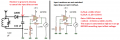
I had recently designed a circuit with a LM 358, which didn't work immediately and I suspected some of the LM 358 to be defective.
In fact I have discovered that depending on the manufacturers, there are some big differences (ie TI, SGS, ...)

So I have found here a schematic for a test circuit and it works.
It's basic but nice, cost effective and simple.

However, is there a possibility to modify it in order that the first OP AMP drives the second one, like it's possible with a CD 4093 schmitt trigger ?

Thanks for your ideas !
 

Attachments

Irving

Joined Jan 30, 2016
3,841
A test circuit for the LM358 or ...? So what does this 'test circuit' actually test? Where did you find it?

And what would the point of connecting #2 to the output of #1 be? What are you trying to achieve? (and its nothing like a CD4093, completely different approach)
 

Thread Starter

Philexium

Joined Oct 15, 2017
85
A test circuit for the LM358 or ...? So what does this 'test circuit' actually test? Where did you find it?

And what would the point of connecting #2 to the output of #1 be? What are you trying to achieve? (and its nothing like a CD4093, completely different approach)
Hi Irving

I am sorry but I am not familiar with OP AMP :-(
The purpose was just to design quickly a "go-no go" circuit

Concerning the CD 4093 it was just an "image" to explain I want to control the 2nd LM358 OP AMP with the 1st one

I mean :
- If the 1st one works and the 2nd too, both are blinking
- If the 1 st one doesn't, the 2nd would not blink

The idea is to identify which one is defective or both !

Hope its clear
 

Irving

Joined Jan 30, 2016
3,841
Ah right, a go/no-go for the LM358... so if it blinks its good? well yes, to an extent.

There is no easy way to connect #2 to the output of #1, and in any case, what happens if #2 is good but #1 bad?~ With your approach you'd never know if #2 was good if #1 is bad. 1/2 a package is still a useful thing...
 

Thread Starter

Philexium

Joined Oct 15, 2017
85
Ah right, a go/no-go for the LM358... so if it blinks its good? well yes, to an extent.

There is no easy way to connect #2 to the output of #1, and in any case, what happens if #2 is good but #1 bad?~ With your approach you'd never know if #2 was good if #1 is bad. 1/2 a package is still a useful thing...
Thank you Irving you have drawn my attention : " you'd never know if #2 was good if #1 is bad"
Yes so tue !
The easiest solution remains to duplicate the crcuit as in the original schematic.
 

Irving

Joined Jan 30, 2016
3,841
Further thoughts, while there are minor variations between manufacturers they shouldn't materially impact on usage unless you're trying to do something the device really isn't appropriate for.. The test circuit is unlikely to tell you much about that...

What were you trying to do?
 

dl324

Joined Mar 30, 2015
16,788
So I have found here a schematic for a test circuit and it works.
You posted a schematic from an AAC member. The polite thing to do, regardless of the source, is to give attribution when you use the work of others.

The original thread by @Ford Prefect.
However, is there a possibility to modify it in order that the first OP AMP drives the second one, like it's possible with a CD 4093 schmitt trigger ?
Why would you want to do that? If one is bad, you need to do more work to figure out which one.
 

Thread Starter

Philexium

Joined Oct 15, 2017
85
You posted a schematic from an AAC member. The polite thing to do, regardless of the source, is to give attribution when you use the work of others.

The original thread by @Ford Prefect.
Why would you want to do that? If one is bad, you need to do more work to figure out which one.
Hi Dennis

Thank you
Sorry I aplogize for forgetting it, I am just a beginner here :) and will remember it

It's for a field strenght meter
 

Thread Starter

Philexium

Joined Oct 15, 2017
85
and...? why didn't it work?
I need the strenght meter to be very sensitive !

Due to the high gain (about 1 000), the offset voltage is multiplied too and so without any HF field the needle of the 100 ua galvanometer is deflecting ...

I am looking for a solution to reduce as much as possible the offset voltage.
Looking at the LM 358 data sheet indicates a min. 2 mV offset.
Please note that I am using a single voltage power supply so I didn't find any solution on the data sheets of the OP AMP.

I know there are some very high performance OP AMP like the LT 1077 with a very low offset but they are very expensive !

I am going to use another OP AMP it will be the best way
Thank you for your ideas
 

Attachments

dl324

Joined Mar 30, 2015
16,788
I am looking for a solution to reduce as much as possible the offset voltage.
You have another thread on this topic. You shouldn't cross post because you'll lose context.
Looking at the LM 358 data sheet indicates a min. 2 mV offset.
That's the typical value, the minimum could be lower. Conservative design would use the maximum.
1635262440520.png
1635262599427.png

It doesn't matter because you've probably been told in the other thread how to null the offset voltage.
 

MrChips

Joined Oct 2, 2009
30,618
Do you have access to an oscilloscope?
I can think of only one way to test the functionality of an op-amp in a simple circuit.
 

Audioguru again

Joined Oct 21, 2019
6,647
I already explained why the field strength meter does not work on your other thread about it. Its + input is not biased at 0V, it floats up because of its positive-going input bias current causing the opamp output to go as high as it can with or without a signal.
 

Irving

Joined Jan 30, 2016
3,841
Re your field strength meter - what frequency is your tank circuit supposedly operating at? The OA85 is a blast from the past!

You will need a lower input offset but that need not cost the earth. Equally problematic with high gain is input noise, you need a low-noise op-amp. LM358 is exactly what you don't need. Here's the problem with the LM358 - the offset is too large so the output is close to the supply rail even with no, or a small, input... also,as has been said, R6 across the input is needed to maintain DC bias as your tank circuit has only a capacitor across the output so is floating.

Note the use of both halves of the device. Gains of 1000 with a single stage are not impossible, but its often better to cascade two stages, here giving 34x followed by 31x for just over 1000. The output volts are converted to a current by R5 and pot X1 and the latter provides a calibration mechanism to adjust for full scale.

1635282399781.png

Replacing the LM358 with something with a much lower input offset allows it to work. Here I've used an AD8572 but there are many suitable parts... The AD8572 is only one example and is only $5 so doesn't break the bank (its a dual device so only one needed).

One caveat - with this low input voltage (< 5mV) and high gain, layout is critical. Making this work reliably on a breadboard is likely to be difficult, if not impossible.

1635283006542.png
 

MrChips

Joined Oct 2, 2009
30,618
I used a TLC555 (or LMC555) CMOS 555-timer circuit to generate a square wave.
R3 and R4 form a voltage divider to attenuate the signal to about 200mV.
You may substitute the 555-timer circuit with a function generator.

The op-amp under test is configured with a moderate voltage gain of -10 (negative because the signal is inverted).
The input is AC coupled via C2 while the non-inverting input is biased at 1/2 Vcc with R7 and R8.

Vcc is a single supply, anything from 5 to 15V.

When examining the output of the op-amp on an oscilloscope, we are looking for four things:

1) output should be centered about 1/2 Vcc
2) voltage gain of 10
3) phase inversion
4) rise and fall times on the transitions


Opamp test circuit.jpg

The first test is with an LM358 op-amp which has a gain-bandwidth product of 1MHz.
LM358.jpg


The second test is with a TL072 op-amp which has a gain-bandwidth product of 5MHz.
Notice the difference in the rise and fall times compared with the LM358. The phase inversion becomes more obvious.

TL072.jpg
 

Thread Starter

Philexium

Joined Oct 15, 2017
85
I used a TLC555 (or LMC555) CMOS 555-timer circuit to generate a square wave.
R3 and R4 form a voltage divider to attenuate the signal to about 200mV.
You may substitute the 555-timer circuit with a function generator.

The op-amp under test is configured with a moderate voltage gain of -10 (negative because the signal is inverted).
The input is AC coupled via C2 while the non-inverting input is biased at 1/2 Vcc with R7 and R8.

Vcc is a single supply, anything from 5 to 15V.

When examining the output of the op-amp on an oscilloscope, we are looking for four things:

1) output should be centered about 1/2 Vcc
2) voltage gain of 10
3) phase inversion
4) rise and fall times on the transitions


View attachment 251223

The first test is with an LM358 op-amp which has a gain-bandwidth product of 1MHz.
View attachment 251224


The second test is with a TL072 op-amp which has a gain-bandwidth product of 5MHz.
Notice the difference in the rise and fall times compared with the LM358. The phase inversion becomes more obvious.

View attachment 251225
Thank you @MrChips !

It's very interesting, a nice circuit and easy to test on my breadboard
Thank you again for your time and help

Best regards from Normandy, France
Philippe
 
Last edited:

Thread Starter

Philexium

Joined Oct 15, 2017
85
Re your field strength meter - what frequency is your tank circuit supposedly operating at? The OA85 is a blast from the past!

You will need a lower input offset but that need not cost the earth. Equally problematic with high gain is input noise, you need a low-noise op-amp. LM358 is exactly what you don't need. Here's the problem with the LM358 - the offset is too large so the output is close to the supply rail even with no, or a small, input... also,as has been said, R6 across the input is needed to maintain DC bias as your tank circuit has only a capacitor across the output so is floating.

Note the use of both halves of the device. Gains of 1000 with a single stage are not impossible, but its often better to cascade two stages, here giving 34x followed by 31x for just over 1000. The output volts are converted to a current by R5 and pot X1 and the latter provides a calibration mechanism to adjust for full scale.

View attachment 251214

Replacing the LM358 with something with a much lower input offset allows it to work. Here I've used an AD8572 but there are many suitable parts... The AD8572 is only one example and is only $5 so doesn't break the bank (its a dual device so only one needed).

One caveat - with this low input voltage (< 5mV) and high gain, layout is critical. Making this work reliably on a breadboard is likely to be difficult, if not impossible.

View attachment 251215
Hi @Irving

The circuit has to be tuned on 144 Mhz (I am a Ham F1 CUJ)

You're right I am using now OA95 , a still old diode but a Germanium one with a low forward voltage, lower than that of silicon

I just had a look at the Analog Device 8572 IC. This is really a very powerful chip !

I see you are using LTspice right ?

It's very interesting, not to be tested on my breadboard I have well understood that.
I use to make circuits with "Manhattan" method with epoxy clads for a quick prototyping
Thank you again for your time and help

Best regards from Normandy, France
Philippe
 
Top