Little challenge

Thread Starter

ranatungawk

Joined Oct 30, 2008
226
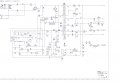
This is a CRT monitor issue. This issue seems to be a power side issue: “no power at all”
Power side circuit diagram is attached herewith.

What I have done: checked the power on the power side.
Findings:
a. 320 DCV at the primary side smoothing capacitor.
b. 320 DCV at the Drain of the MTP6N60 FET, but 0V at G and S pin.
c. 320 DCV at the 13 pin of the Choper transformer (between 13 pin and (-) of the smoothing cap)
d. 320 DCV at the 14 pin of the Choper transformer (between 14 pin and (-) of the smoothing cap)
e. However no any voltage (0V) appear at the secondary side of the chopper

Note: Just forget the chopper , it’s tested and verified ., the wrong should be another point. Pls tell me how to troubleshoot this
 

Attachments

panic mode

Joined Oct 10, 2011
4,979
voltage at drain (pin14 of transformer) is 320VDC because transistor is not working. you need to see why there is no pulse train at the gate of transistor and if it is present at pi6 of the comparator IC. also check supply voltage at pin7 of SMPS IC (Vcc).

as mentioned 100k 3W resistor (3135) is used to start the circuit but when the comparator starts producing pulses, it would get permanent power from the transformer (rectified from pin11 of the transformer).

measure voltage at check points C1, C2, C3
 

Thread Starter

ranatungawk

Joined Oct 30, 2008
226
voltage at drain (pin14 of transformer) is 320VDC because transistor is not working. you need to see why there is no pulse train at the gate of transistor and if it is present at pi6 of the comparator IC. also check supply voltage at pin7 of SMPS IC (Vcc).

as mentioned 100k 3W resistor (3135) is used to start the circuit but when the comparator starts producing pulses, it would get permanent power from the transformer (rectified from pin11 of the transformer).

measure voltage at check points C1, C2, C3[/QUOTE

thanks for the information !

1. i tested the transistor by replacing it
2. no voltage at pin 6 of the SMPS ic
3. starting up voltage is 5v (not the 12V - 15V as it should be) at the 7pin
4. i didn't check the voltage at C1, C2, C3 , but sure voltage should be 0

so ..?
 

John P

Joined Oct 14, 2008
2,061
LCD monitors are cheap these days, don't use much power, don't take up much space, are easy to move around--I'd say you have an excuse to dump the CRT (in an ecologically sound manner, of course) and shift to LCD.
 

timescope

Joined Dec 14, 2011
298
Hi ranatungawk,
1. Check the collector - emitter of opto-coupler 7112 for short circuit
2. Remove uc3842 and check the associated components especially the auxillary winding diodes 6112 and 6125.
3. If all components are ok, replace the uc3842 with a new one.
The picture quality of crt monitors is much better than LCD monitors.
Timescope
 

panic mode

Joined Oct 10, 2011
4,979
1. i tested the transistor by replacing it
2. no voltage at pin 6 of the SMPS ic
3. starting up voltage is 5v (not the 12V - 15V as it should be) at the 7pin
4. i didn't check the voltage at C1, C2, C3 , but sure voltage should be 0

so ..?
1. replacing something is not test. for all we know, new one could be damaged by handling/soldering.
2. 0V?
3. Vcc is supposed to be 15V and produce Vref at pin6 which is 5V
4. you kidding right? you have only 8-pin chip and you don't bother to check and record all voltages?

main problem is that you get much less than 15V for supply. a bit less would be expected but maybe something else is shot and sinking too much current. US3842 shoulddraw less than 15mA according to datasheet. if the supply is only 5V, no wonder IC is in lockdown.
 
Top