That's because you're not subtracting the Forward-Voltage-Drop of all of the LEDs.
This is going to be at least 2-Volts each, and possibly more than 3-Volts each.
.
.
.
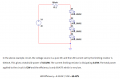
LED voltage = 20 volts - ( 0.600 Amps)(10.2 ohms)
LED voltage = 13.88 volts
Individual LED voltage = 3.47 volts
Each LED consumes 2.1 watts ( = 0.60 A* 3.47 V)
All four consume 8.4 watts
The voltage source provides 12 watts (20 V * 0.6 A)
The series resistor consume 3.6 watts ( 12 watts - 8.4 watts)
Efficiency 69%
Yea there are calculators out there for fun.
Of course best way is always build/ test/ tweak.
This is one " solution" from one based on your initial parameters Its a crummy array. 5 LEDs is much
better. Only approx 2 wasted watts out of 12..
As to the calculator there is some discussion on it's " correctness"..
These Buck converters feature 9VDC to 36VDC input and 2VDC to 32VDC output (LDD-L) or 9VDC to 56VDC input and 2VDC to 52VDC output (LDD-H). A wide range of output current options are available from 300mA to 1A. The LDD DC-DC Converters from MEAN WELL have an extremely high-efficiency level of 97%. These drivers feature a built-in EMI filter and comply with the EMI lighting requirements of EN55015.
Thanks for the interesting circuit.. Now I just have to figure out why it says "adjust resistor value to 2.2v at the desired current."
Also I as-u-me that leds need to be matching..for current balancing.
Unlike the ldd which you can string mis-matched (different V(f)'s) leds together with no issues afaict.
The Schematic that I provided was strictly to generate ideas.
It was for a particular application that a previous Thread-Starter wanted.
Notice that it is rated for 60-Volts max.
The original idea was to have the LEDs connected in series, and running on a relatively high-Voltage.
The 2.2-Volts is the Feedback-Threshold-Voltage used normally for Voltage-Regulation,
only in this case, the Chip is setup as a Current-Regulator, with a Current-Sense-Resistor.
The Current-Calculation-Formula for the Resistor is included in the Schematic.
This Chip is rated for ~5-Amps,
and comes in a TO-220-5 Package for great Heat-Dissipation,
whereas most High-Power-LEDs are rated at significantly less than 5-Amps,
this generally provides a comfortable Power-Handling margin.
And, it requires no external Components other than the standard Filter-Components.
The "7-Pin"-version has a "Standby-Pin" if PWM Dimming is desirable,
and a "Peak-Current-Limiting-Pin" for averting "accidents".
The Feedback-Pin on the 5-Pin-version can also be used for PWM Dimming,
in fact, that may be the preferred method of PWM-Dimming,
but I haven't looked into it that carefully.
I don't know how stable the "fresh-start-up" would be using the "Standby-Pin" with PWM.
.
.
.
 Facebook
 Google
 GitHub
 Linkedin
 29.8 KB Views: 17


