
 Facebook
 Google
 GitHub
 Linkedin
So I've been trying to figure out what I'm doing wrong regarding a theoretical aspect of this lab. I've used both ideal analysis and experimental analysis and can't figure out if I'm doing this right.
The circuit is shown produced in Multisim below:
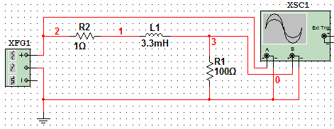
The function generator produces a sine wave of 10 Vp, 1 kHz, 0 V DC offset
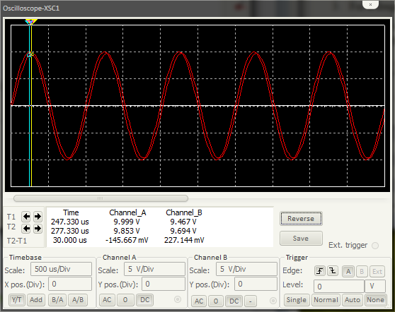
The corresponding OSCOPE window is shown below with the peak values indicated and the time delay given:
My lab manual says that the line impedance is given by this equation:
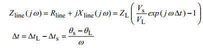
It gives the derivation of this formula based on a similar circuit where Z_load is the load measured and Z_line is represented by the line impedance.
So given:
Z_L = 100
V_S = 9.999 V
V_L = 9.694 V
dt = 30e-6 s
ω = 2πf = 2 * pi * 1000
Input into MATLAB:
From the answer:
R_line = 1.3193 ohm =/= 1 ohm (but close enough?)
X_line = 19.3277 = jwL --> 19.3277/1000 = L = 1.93 mH =/= 3.3 mH
Keep in mind this is all done in Multisim, which I thought is supposed to be pretty close if not actually ideal measurements. I'm not sure what I'm doing wrong, or if indeed these are the correct values that I'm supposed to obtain. The lab manual mentions compensating reactance which is the negative X_line to correct the power factor to 1.
Power tends to go over my head so I'd be most grateful if anyone could clear up the problem I'm having. Needless to say that since I'm confused in the ideal, theoretical case, I'm not getting anywhere in the experiments where I utilize these equations.
I analyzed the circuit on pen and paper through a voltage divider:
V_L = 10e^(j0) [ (100)/(100+j3.3) ] = 10e^(j0) * 100 / (101.05e^(j*1.87))
V_L = 9.896e^(j*-1.87)
Not getting anywhere with that either.
Edit: It appears the the first couple of cycles in the oscilloscope does not always lead to steady voltage, as opposed to letting the simulation run for a few seconds and then measuring the peak voltages at the end of the reading. The difference is minor, a few mV, and the results are still similar to the above problem.
Edit 2: I think I figured it out but I could still use some input. The Z_line I've been getting that I think is wrong gives the value I need for a correcting capacitor of 1/(w*X_line)... When putting that in series the pf goes to 1. I guess Z_line is not supposed to be calculated to any sort of ideal value?
The circuit is shown produced in Multisim below:
The function generator produces a sine wave of 10 Vp, 1 kHz, 0 V DC offset
The corresponding OSCOPE window is shown below with the peak values indicated and the time delay given:
My lab manual says that the line impedance is given by this equation:
It gives the derivation of this formula based on a similar circuit where Z_load is the load measured and Z_line is represented by the line impedance.
So given:
Z_L = 100
V_S = 9.999 V
V_L = 9.694 V
dt = 30e-6 s
ω = 2πf = 2 * pi * 1000
Input into MATLAB:
This does not seem to agree with what I know about the ideal line transmission! Why does this happen?>> 100*((9.999/9.694)*exp(i*2*pi*1000*30e-6)-1)
ans =
1.3193 +19.3277i
From the answer:
R_line = 1.3193 ohm =/= 1 ohm (but close enough?)
X_line = 19.3277 = jwL --> 19.3277/1000 = L = 1.93 mH =/= 3.3 mH
Keep in mind this is all done in Multisim, which I thought is supposed to be pretty close if not actually ideal measurements. I'm not sure what I'm doing wrong, or if indeed these are the correct values that I'm supposed to obtain. The lab manual mentions compensating reactance which is the negative X_line to correct the power factor to 1.
Power tends to go over my head so I'd be most grateful if anyone could clear up the problem I'm having. Needless to say that since I'm confused in the ideal, theoretical case, I'm not getting anywhere in the experiments where I utilize these equations.
I analyzed the circuit on pen and paper through a voltage divider:
V_L = 10e^(j0) [ (100)/(100+j3.3) ] = 10e^(j0) * 100 / (101.05e^(j*1.87))
V_L = 9.896e^(j*-1.87)
Not getting anywhere with that either.
Edit: It appears the the first couple of cycles in the oscilloscope does not always lead to steady voltage, as opposed to letting the simulation run for a few seconds and then measuring the peak voltages at the end of the reading. The difference is minor, a few mV, and the results are still similar to the above problem.
Edit 2: I think I figured it out but I could still use some input. The Z_line I've been getting that I think is wrong gives the value I need for a correcting capacitor of 1/(w*X_line)... When putting that in series the pf goes to 1. I guess Z_line is not supposed to be calculated to any sort of ideal value?
Last edited:






