Light Sensitive Circuit with LDR ( Light dependent Resistance )

Thread Starter

sanmakk1001

Joined Jul 13, 2014
18
Hey guys! I hope you are fine. I am looking for some sort of help on LDR (Light dependent Resistance). I am not very much good in building circuit. But I hope that your help can make it easy for me.

I planned to build a small light sensitive circuit using LDR.
Here is the list of things which I planned to use:

1- 2 White LEDs ( 5mm) (forward current =20mA) (Forward voltage = 3.5 )

2- LDR

3- Input Voltage 4.0 volts

4- Sensitivity control ( Potentiometer )

5- Transistor

6- Switch

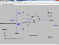
Now I have tried one circuit which I found on the internet. It uses an NPN transistor 3904 and worked with only one RED LED which requires less current as compared to the white LED.
2104863039_a966a485e5_o.jpg

The second thing I am worried about is sensitivity. I want to make it too sensitive that it only light up when there is no light. So can you kindly help me to make that possible?
 

wayneh

Joined Sep 9, 2010
17,496
The only tool you have in that circuit is the 1k resistor. Try changing it by placing other resistors in parallel or series with it, to fine tune the resistance to get the behavior you want.

The 2N3904 turns on when the voltage on its base exceeds the emitter voltage by ~0.65V. The red LED turns on at some voltage (lower than a white one, that's why it works here), let's say it is 2V. So you need the voltage at the base to be 2.65V to just start the LED. You can tune the value of the resistor, relative to the value of the phototransistor when it is at the light level you want, to get that 2.65V onto the base of the transistor. All values are estimates, and depend on the actual properties of your devices.

Bottom line, you may not be able to get a significant improvement with such a simple circuit. It's performance will also change as the battery ages.
 

ronv

Joined Nov 12, 2008
3,770
A couple of questions:
The diagram shows a coin cell. They are normally 3.7 volts for rechargeable but only 3 volts for regular.. Is that what you want to use? If so which one?
2 LEDs at 20 ma each???
How long do you want it to last?
 

Alec_t

Joined Sep 17, 2013
14,280
With a Vf of 3.5V and a Vbe of 0.6V your supply needs to be > 4.1V. To light 2 LEDs in series would need at least 7.6V. With 2 LEDs in parallel instead, the current could approach 40mA max. The battery won't last long.
 

Thread Starter

sanmakk1001

Joined Jul 13, 2014
18
Yeah sorry guys I almost forgot to talk about batteries. I planned to use 3-AA 1.5v each rechargeable batteries. So I tested when they are fully charged they give me 4.0v. So what you guys suggest me further. Anyhow thanks for quick response. I have learnt many thing new..:)
 

Thread Starter

sanmakk1001

Joined Jul 13, 2014
18
Yep right 5v. I checked today after charging them. Yeah I tired this circuit with LDR. I just got just LDR for this project. Now I am little confuse. I know I can use appropriate resistor with two white LED's and What about LDR and Transistor will they survive 5v Sorry I have no idea..??
 

Thread Starter

sanmakk1001

Joined Jul 13, 2014
18
The only tool you have in that circuit is the 1k resistor. Try changing it by placing other resistors in parallel or series with it, to fine tune the resistance to get the behavior you want.

The 2N3904 turns on when the voltage on its base exceeds the emitter voltage by ~0.65V. The red LED turns on at some voltage (lower than a white one, that's why it works here), let's say it is 2V. So you need the voltage at the base to be 2.65V to just start the LED. You can tune the value of the resistor, relative to the value of the phototransistor when it is at the light level you want, to get that 2.65V onto the base of the transistor. All values are estimates, and depend on the actual properties of your devices.

Bottom line, you may not be able to get a significant improvement with such a simple circuit. It's performance will also change as the battery ages.

Exactly Right..! I didn't know that before Thank you soo much. And what about using BC 547 and 2n2222 instead. Just give me your Suggestions about using them
 

Thread Starter

sanmakk1001

Joined Jul 13, 2014
18
Batteries sound more like 1.2 V?? Ni-mh ? If so 4 will give about 5 V. You show photo transistor & specify LDR ?
Yep right 5v. I checked today after charging them. Yeah I tired this circuit with LDR. I just got just LDR for this project. Now I am little confuse. I know I can use appropriate resistor with two white LED's and What about LDR and Transistor will they survive 5v Sorry I have no idea..??
 

wayneh

Joined Sep 9, 2010
17,496
And what about using BC 547 and 2n2222 instead.
Funny thing about transistors, they're essentially all the same in this regard. Any NPN BJT you pick will need the same ~0.6V on its base (relative to the emitter) in order to start conducting. For your simple LED circuit, it doesn't much matter which transistor you choose.

Of course there are other types of transistors beyond the scope of this discussion.

If you use more powerful battery packs, you'll need a resistor to limit current to the LED. You got way without one because of the low voltage and small size (high internal resistance) of the coin cell.
 

ronv

Joined Nov 12, 2008
3,770
Maybe you can post a link to the data sheet for the LDR?
The 547 will be good, but I worry it won't turn off.
 

Thread Starter

sanmakk1001

Joined Jul 13, 2014
18
Funny thing about transistors, they're essentially all the same in this regard. Any NPN BJT you pick will need the same ~0.6V on its base (relative to the emitter) in order to start conducting. For your simple LED circuit, it doesn't much matter which transistor you choose.

Of course there are other types of transistors beyond the scope of this discussion.

If you use more powerful battery packs, you'll need a resistor to limit current to the LED. You got way without one because of the low voltage and small size (high internal resistance) of the coin cell.
NO dude. I listed above that I planned to use 5V Battery 4AA Rechargeable each 1.2v. What do you prefer now..?
 

wayneh

Joined Sep 9, 2010
17,496
What do you prefer now..?
What Bernard drew. Having more voltage to work with 1) mandates using the resistor to control LED current, and 2) allows using a darlington as Bernard has shown. A Darlington is two transistors, and so the base voltage must be twice as high, or about 1.2V, for conduction to start. In exchange for that you gain an extra stage of amplification. This will allow you more sensitivity when you are setting the switching point determined by the LDR and the pot.

If you want 2 LEDs in series with only 5V for the supply, you probably cannot use a Darlington.
 
Top