LED Wiring Help Needed ASAP

Thread Starter

HardwoodInc

Joined May 23, 2015
8
Hello everyone,
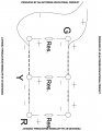
I am a woodworker specializing in display stands. I have been installing LED's in my displays for some time now and continually run into the same issue - I frequently get requests for a setup of Red, Yellow, and Green LEDs in a particular display (see pic). The problem is that these lights have different forward voltages, and the greens always end up significantly brighter than the yellow and red. Here are the specs for the LEDs:

Green: 3.0 - 3.4v 20mA - 12000 mcd
Yellow: 1.8 - 2.2v 24mA - 12000 mcd
Red: 1.8 - 2.2v 24mA - 12000 mcd

Supply Voltage: 9v

I have tried wiring them both totally in series, which does not light whatsoever, and in parallel, in which case the brightness is the issue. I have seen pairs of LEDs in series then wired in parallel but i'm totally confused about that one. I have tried multiple different resistors suggested by online calculators, in every location of the circuit I can think to try. But nothing seems to even out the brightness. I have very little knowledge of electronic circuits so I'm hoping someone will be kind enough to propose a solution, because I'm just stabbing in the dark at this point. I've attached a diagram of how the LEDs are laid out, if any further information is needed please let me know. Thanks for your time and help in advance!

xtraminiLED.jpg
 

Attachments

Wendy

Joined Mar 24, 2008
23,415
Sounds like you don't really understand LEDs. Start, show a schematic, the language of electronics.

It is not dropping voltage, but current that matters.

LEDs, 555s, Flashers, and Light Chasers

If you read the article you will note that LEDs should never be directly in series with each other, they should be part of a leg or string.

Correction: I meant to say "directly in parallel with each other,".
 
Last edited:

shteii01

Joined Feb 19, 2010
4,644
The basic problem, as you have noted yourself is that greed uses different voltage.

1) So the simplest thing to do is to use greed led that have the same forward voltage as the other two colors.
2) Next simplest thing to do is to use two power supplies, one for the green, second for yellow and red.
3) Next simplest thing to do is to use the single power supply and use power regulator for the green, this way you would have 3-3.4 volts for green and have 1.8-2.2 volts for other colors.

Is any of the above possible for you?
 

wayneh

Joined Sep 9, 2010
17,496
I would do the following: 1) Wire each pair of colored LEDs in series with each other - red with red, green with green, and so on. 2) Choose a resistor to place in series with each string. The resistor should limit the current to <20mA (I'd aim for 15mA if I need the light, maybe 5-10mA if it's just for looks). 3) Put the 3 colors in parallel to the 9V source. Tweak the resistor values until the relative color levels are pleasing. This will likely mean running the red LEDs at a higher current than the green, by reducing current (adding resistance) to the green leg.

If your 9V battery won't light two LEDs in series, it's getting old and is no longer at 9V. I believe some rechargeable 9V batteries are actually 7.2V, and this may not be a great choice.
 

dl324

Joined Mar 30, 2015
16,845
Green: 3.0 - 3.4v 20mA - 12000 mcd
Yellow: 1.8 - 2.2v 24mA - 12000 mcd
Red: 1.8 - 2.2v 24mA - 12000 mcd
Would have been nice if you had described how the LEDs were connected. The bottom line is that the brightness for all of the LEDs is specified at 24mA; that's how I'm interpreting the data you gave. So run them at the same current to get similar brightness.

You say that green was the brightest, but if you're driving all with the same series resistance, green should have been the dimmest. Until you consider that most males are more sensitive to green...

Our eyes respond to light logarithmically and differently for each color; so what you're after is subjective...
 

Wendy

Joined Mar 24, 2008
23,415
The basic problem, as you have noted yourself is that greed uses different voltage.

1) So the simplest thing to do is to use greed led that have the same forward voltage as the other two colors.
2) Next simplest thing to do is to use two power supplies, one for the green, second for yellow and red.
3) Next simplest thing to do is to use the single power supply and use power regulator for the green, this way you would have 3-3.4 volts for green and have 1.8-2.2 volts for other colors.

Is any of the above possible for you?
Again, it is current, not voltage that matters. The only thing dropping voltage is used for is to calculate the resistance needed for that chain of LEDs, each chain would have a different value resistor with the goal of setting up the same current in that chain. You do not set a power supply voltage to drive the LED, as this post would seem to suggest.

The article I suggested does explain this in 2nd post.
 

shteii01

Joined Feb 19, 2010
4,644
Again, it is current, not voltage that matters. The only thing dropping voltage is used for is to calculate the resistance needed for that chain of LEDs, each chain would have a different value resistor with the goal of setting up the same current in that chain. You do not set a power supply voltage to drive the LED, as this post would seem to suggest.

The article I suggested does explain this in 2nd post.
You are right.
 

Thread Starter

HardwoodInc

Joined May 23, 2015
8
I would do the following: 1) Wire each pair of colored LEDs in series with each other - red with red, green with green, and so on. 2) Choose a resistor to place in series with each string. The resistor should limit the current to <20mA (I'd aim for 15mA if I need the light, maybe 5-10mA if it's just for looks). 3) Put the 3 colors in parallel to the 9V source. Tweak the resistor values until the relative color levels are pleasing. This will likely mean running the red LEDs at a higher current than the green, by reducing current (adding resistance) to the green leg.

If your 9V battery won't light two LEDs in series, it's getting old and is no longer at 9V. I believe some rechargeable 9V batteries are actually 7.2V, and this may not be a great choice.
Thanks for your response. I've attached a picture with the best version of a wiring diagram I could come up with. Is this the type of layout you were referring to? Or do the resistors go between the strings in parallel? And when I calculate resistor values I will just do them for each string (pair of lights) and then tweak from there correct? Thanks again for the help.
 

Attachments

Wendy

Joined Mar 24, 2008
23,415
Cal you rea schematics? It really is the language nof electronics. I would be glad to help, but we have to speak a common lingo.
 

Thread Starter

HardwoodInc

Joined May 23, 2015
8
Cal you rea schematics? It really is the language nof electronics. I would be glad to help, but we have to speak a common lingo.
Somewhat, if they're well labeled ;). As I said, i'm a woodworker, not too familiar with electronics. I gave my best shot on that "schematic" I attached ha, but I can try to decipher one if you're willing to help.
 

djsfantasi

Joined Apr 11, 2010
9,156
I noticed that the green LED is rated at a lower current that the others. You haven't mentioned how the module is wired, nor if it is using any resistance at all. But current limiting resistors are required for LEDs (except in very rare cases).

So the calculation for the resistor required for the pair of green LEDs would use a current of 20mA and a voltage of 2.4V across the resistor (I used the midpoint of the forward voltage range):

\(\small{R=(\frac{(9V-2*3.2V)}{.02A})=130\Omega}\)
which is a standard 5% resistor value.​


For both the red and yellow pairs of LEDs, use a current of 24mA and a voltage of 5.0V across the resistor:

\(\small{R=(\frac{(9V-2*2.0V)}{.024A}=208\Omega}\)
In this case, the closest standard resistor is \(\small{220\Omega}\).​

If you want to run at a lower current, you can use the equations above to calculate the resistor value for each pair.
 

djsfantasi

Joined Apr 11, 2010
9,156
Here is a schematic, showing the wiring of the six LEDs. Note as I said in my last post, that the calculated value of the resistors is for the maximum current specified in the LED datasheets. To run them at a lower current, use the formulas to recalculate the values. Or as @wayneh suggested, tweak the resistor values until you get the effect that you want. That is, to run the red and yellow LEDs at 18mA instead of 24mA, use a 300Ω resistor. That is 75% of the specified current, so 75% of 20mA is 15mA for the green LED. In that case, you would use a 180Ω resistor.
Capture.PNG
 

djsfantasi

Joined Apr 11, 2010
9,156
The actual location of the resistors within the series connections is irrelevant. Whichever way you understand it better. I drew it the way I would wire it.
 

Thread Starter

HardwoodInc

Joined May 23, 2015
8
Think I got it all figured out. Thanks for the quick help everybody! I wired it like the schematics showed and played with the resistors for a little while until all the lights looked good and evenly bright. Learned some new stuff thanks to you guys, and I'll keep reading the suggested articles to learn some more!
 

Thread Starter

HardwoodInc

Joined May 23, 2015
8
Sounds like you don't really understand LEDs. Start, show a schematic, the language of electronics.

It is not dropping voltage, but current that matters.

LEDs, 555s, Flashers, and Light Chasers

If you read the article you will note that LEDs should never be directly in series with each other, they should be part of a leg or string.

Correction: I meant to say "directly in parallel with each other,".
Why is wiring them in parallel not recommended? I've been doing this with almost all my single color setups :/
 
Top