LED to monitor current flow

Thread Starter

Trippynet

Joined Jun 17, 2017
3
Hello,

I have a solar trickle-charger for my motorcycle. It's currently connected to the bike via the accessory socket on the bike (similar to the cigarette socket on a car). Problem is, I've had a couple of occasions either with one of the connectors linking it not making a good contact, or the plug into the bike being disturbed and hence not making a good connection.

As it currently stands, I have no way of knowing whether or not the solar charger is actually charging the bike (well, until I fancy a ride and find the battery is flat because it wasn't charging as I thought), so I'd like to add a simple LED into the circuit that illuminates if there is a current flow. The charger outputs around 12v, and is rated for up to 2.4w / 138mA - although the output will of course vary depending on weather conditions.

Can anyone advise how to add an LED to the circuit to show whether there is current flowing - but without significantly impeding the performance of the charger (other of course than the power required to drive the LED)?

My searches so far haven't really found what I'm looking for.

Many thanks in advance!
 

dl324

Joined Mar 30, 2015
18,445
Welcome to AAC!
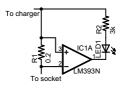
Can anyone advise how to add an LED to the circuit to show whether there is current flowing - but without significantly impeding the performance of the charger (other of course than the power required to drive the LED)?
upload_2017-6-17_7-54-16.png
This circuit assumes that the offset voltage of the comparator won't turn on the LED with no current in R1.

You can decrease LED current if desired, you just need it to be bright enough for you to tell it's on.

I assume there's a blocking diode in the solar panel. This circuit needs to be between the solar cells and the blocking diode. If that point isn't accessible, you need to add a schottky diode between R1 and the socket.
 

Sensacell

Joined Jun 19, 2012
3,786
This circuit is a little problematic: what's not shown is the power connections for the chip- for this to work, the inputs must be within the common mode range of the chip, (Vcc - 1.5V) it would need a Vcc voltage higher than the battery voltage to function correctly.
 

crutschow

Joined Mar 14, 2008
38,627
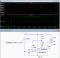
Or use a circuit that monitors the negative side current to avoid the LM393/339's common-mode limits:
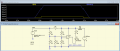
R3 and R4 add some offset and hysteresis to minimize oscillations at the trip point and insure that the LED is off for no current.

upload_2017-6-17_14-59-53.png
 

Attachments

Last edited:

spinnaker

Joined Oct 29, 2009
7,830
Hello,

I have a solar trickle-charger for my motorcycle. It's currently connected to the bike via the accessory socket on the bike (similar to the cigarette socket on a car). Problem is, I've had a couple of occasions either with one of the connectors linking it not making a good contact, or the plug into the bike being disturbed and hence not making a good connection.

As it currently stands, I have no way of knowing whether or not the solar charger is actually charging the bike (well, until I fancy a ride and find the battery is flat because it wasn't charging as I thought), so I'd like to add a simple LED into the circuit that illuminates if there is a current flow. The charger outputs around 12v, and is rated for up to 2.4w / 138mA - although the output will of course vary depending on weather conditions.

Can anyone advise how to add an LED to the circuit to show whether there is current flowing - but without significantly impeding the performance of the charger (other of course than the power required to drive the LED)?

My searches so far haven't really found what I'm looking for.

Many thanks in advance!
How big is your panel? Do you care if it will take longer to charge with the LED than without it? any device you have to monitor the current will take current that can be charging the battery.
 

ErnieM

Joined Apr 24, 2011
8,415
Hello Trippynet, welcome to the forums.

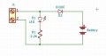
I see a lot of fancy things here with lots of parts, while all you really need is something to let you know you have a connection. I would just do this:

Conn.jpg

Your connector and battery are on the left & right side. You need break the + lead to stuff a diode in there. Then the solar panel can light the LED when it is connected and the sun is shining bright.

This does waste a bit of power in the D2 diode needed to isolate the battery from the solar panel. A Schottky type diode may be better, but I would start with any ole power rectifier diode.

If you tell us where you are we can help you find these parts, but EBay may be your best (albeit slow) friend.
 

Thread Starter

Trippynet

Joined Jun 17, 2017
3
Hello,

Many thanks for the suggestions so far, really appreciate it! To be honest, I'm glad it's not a ridiculously simple and unanimous solution that would have had me banging my head and saying "why didn't I think of that?".

To answer a couple of queries, I'm aware of course that the circuit will pull a small amount of power from the solar panel, but I'd like to try and minimise any hit on charging if I can. As I live in Scotland, we don't exactly get the sunniest weather as it is! Hence, a small hit is fine. A significant reduction in charging power might be a bit more troublesome. Of course, I'd also need to ensure that during the night, the circuit can't pull accidentally drain power from the battery...

The first solution looks promising, thank you for that dl324. You state to substitute a comparator with rail to rail inputs, given my admittedly rusty and fairly rudimentary electronics knowledge, can you clarify what you'd mean for this?

Many thanks again for the suggestions so far!
 

Thread Starter

Trippynet

Joined Jun 17, 2017
3
Hi everyone, just a quick update. In short, I now have a charging LED, and with pretty much zero impact to the charging circuit.

I had the simple brainwave that I don't need the LED to be permanently lit (after all, the trickle charger will spend 99% of its time in the garage un-monitored), I just needed a quick way to be able to check from time to time and ensure the charger is indeed feeding the bike properly.

Bearing this in mind, I ended up simply wiring a 3 pole push-button switch up with an LED+resistor (mounting it all in a little box of course). Under normal conditions, the solar charger is providing 100% power to the bike battery. If I press the button, it routes the current through the LED and shows me easily if the charging circuit is working or not.

Ultimately, this seemed the best approach regarding keeping things simple whilst effectively eliminating any impact on the charging circuit. Many thanks for the suggestions previously, they were appreciated!
 
Top