LED prop project for a Dr Who double

Thread Starter

Fenris

Joined Oct 21, 2007
288
Hi Bill

Cheers :D It's great! Really enjoying myself at the moment. A 6/42............Now that would be outstanding. 6 pot controls sounds good. Would 100K pots suffice and I would need to keep a resistor in line I guess for when the pot is set to minimum.

Talking of pots. When the wiper and one end of the track are joined what actually happens? Does a 100K pot become 50K or is the effect more subtle?

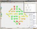
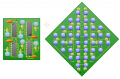
The Christmas tree effect is purely down to adhering to your schematic but it was what I thought of your layout when I first saw it :D Stretching the LED's out would indeed add to the overall effect of pseudo randomness.

I will attempt to work out how to draw up the 6/42 by extrapolating from your original........ But it's more likely I'll scream for help :D The 556 IC's make for a nice compact dual timer part of the circuit and considerably neater in layout. I will have to consider the most interesting layout of the LED's for best effect.

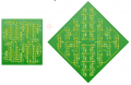
Perhaps a 2 PCB layout? The chips one and the LED's on the other. Perhaps the pots could be hardwired to the Timer PCB around its periphery. Circular or square?

42 Blue LED's doing their thing I can't wait :D

I like your long life LED circuits. As you remarked on, I to miss the 3909. It was the first LED IC circuit I built that worked. My Mrs thinks I am a clever chap. I correct her on this fact, if I was clever I wouldn't need to ask for help with this hobby all the time. The only project that irritates her though is the Dalek voice box............... I have built over 30 and tested everyone of them prior to sending them out. I guess it would grate on the nerves a bit :D.

My Step son is now interested in a circuit to do a Blue LED chaser light for the lip of the front spoiler on the car in the pattern of the 'night rider' lights. So the triple 4017 circuit with the 2N7000 mosfet mod and signal diodes to effect the sweep action of the LED's.............. So much to do so little time!

regards

Fenris
 
Last edited:

Wendy

Joined Mar 24, 2008
23,421
My experience with 555 Hysteretic Oscillator is that you don't need the extra resistor, though it is handy to set a maximum range. In theory you should, but it's OK either way. In this case I would add it, since I would want the range to be around 1Hz to 100Hz. My concept is multicolor, what would be really neat is to have some RBG LED diodes so I could have more than one color per location, that or allow the user to select what color they like. RGB diodes are beyond reach at the moment, at least in quantity, so it'll wait.

My boy (19) really liked your current work in the ball. He wants me to make one. My stance is he needs to learn how to solder. So much to do, so little time!

I never take asking for advice as a sign you're not smart, you just haven't had time to learn it all yet.

Don't try for the 6/42, at least not yet. It will need drivers, if I can find complementary FETs like Wookie suggested that would do it. That would work out to 2 transistors and 1 resistor per output (12 FETs total, 6 resistors). For a straight 555 you would need to dim the LEDs to compensate. Since half the LEDs are on at any one time, figure you would have to power 21 per 555, which puts it around
7 ma / LED.

You wouldn't believe how complicated (as in busy) that schematic was when I first drew it, I kept tweaking it until it looked simple. That seems to be one of my knacks.
 

Thread Starter

Fenris

Joined Oct 21, 2007
288
Hi Bill

Thanks for that. I just realised thats all I did with the 4017 circuit and it's fine :D I remember in your article for the 4/20 you said that the ramp up in amps drawn got quite large. So 2 FET's per output, that would be so you can handle the +ve and -ve going cycles yes?

Cor an RGB setup would look good. Complicated to I'd warrant. I'll stick with the 4/20 I'll still do the dual board though for a 4/20 x 2.

I will clean up the PCB's in terms of the extra bit I had on the 2nd one, the beeper, and do a parts list for it. Once thats sorted I will pop the component side and the artwork up with a scale reference. Theres so few parts to it really is simple.

The current iteration has the PCB's back to back so the rotation is naturally opposite directions. I am thinking of moving the second 4017 onto its own board so that there is one PCB with the 555, a 4017 and it's own LED's and a PCB with a 4017 and it's own LED's. This will mean having a flaying wire from the 555 to the second PCB to drive it.

I'm going to look and see if there is a way for the amateur to do plate through holes so that the PCB's can be brought really close together using the solid copper wire pillar technique as used on the prop. Then all the support and power/signal rails can be soldered on the component side of one of the PCB's when fitted together closer than a soldering iron can get through.

You, indeed, have a gift for making the schematics nice and readable. You still have to keep on your toes with the 4/20 to avoid missing links out when bread boarding though :D

OH and I had a thought on the 4/20 circuit. The output (pin3) of each timer goes to a rotary switch so that they end up driving different LED's as you rotate it. This would change the pattern as well.

Regards

Fenris

PS what happens to a pot when you tie the wiper and one end together?
 
Last edited:

Wendy

Joined Mar 24, 2008
23,421
Yeppers, the difference between 4/20 and 6/42 is 100ma vs. 210ma. A 555 is rated for 200ma, so there you are. In your case the battery drain between 2X4/20 and one 6/42 is about the same, and I suspect you'd have trouble telling the difference.

I'm thinking of adding a new chapter to the LEDs and flashers article. There is a way of using only resistors and LEDs to make a simple, sloppy bargraph. The sucker works, but the math is slightly convoluted. It is also what I call mushy, the line between light and dark LEDs is about 3 LEDs worth, but the eye averages details like that quite nicely.

Let us know how the projects going. While some of the base episodes can be pretty bad, I am a firm fan of Dr. Who. Just wish some of their writers had more science background. Tom Collins and Jon Pertwee were my favorites. I remember one episode with Jon where he completely dismantled a AM radio and made a transmitter. Implausible, but not impossible. He did what he needed, and was standing there admiring his work (like any of use would do) when the rig caught on fire.
 

Thread Starter

Fenris

Joined Oct 21, 2007
288
Hi Bill

I'm paying attention it seems :) . The 4/20 bread board has been running for hours now and seems quite content!

Jon Pertwee was my first exposure to Dr Who. He was great but I wasn't a real fan though I was always a bit put out if Mum and Dad thought we should go out over the weekend and I'd miss an episode. Tom Baker was my Dr, who, I came to admire in my childhood. He was MY Dr :D Yes the science was way off if you new your stuff but it was fun. Modern Sci Fi series such as Star Trek TNG did a lot to pull their science from real world science's even if a lot of it was only theory but it upped the bar in terms of the quality of the 'real world' background within the shows for the fans of such programs.

The 4017 circuits are pretty much sorted :D I am beginning the PCB design for the 4/20 x 2.

Regards

Fenris
 

Thread Starter

Fenris

Joined Oct 21, 2007
288
Here's the layout of the LED's. Ignore the colours they are just for reference of the groups so I can follow the inter-wiring. It has 40 LED's. I am hoping that it increases the sense of randomness so that the 2 halves look as if they are a single circuit.

It is laid out in the cockeyed manor due to the limits of the rotation the software allows. 90 degree increments only.

I have been playing with the capacitor values. Slowing the flashing down and speeding it up. It's fun :D

regards

Fenris
 

Attachments

Thread Starter

Fenris

Joined Oct 21, 2007
288
Hi all

I redid the LED layout it was just a bit pants I think. Second version came about a bit easier though. If you look carefully at the LED PCB you can see it has three main groups. Left, Right and Middle. The ones in the middle are the LED's that are fixed closest to Pin 3 of the 555's in Bills original schematic. and the Left and Right sides are the remainder of the 'tree'. This is a 4/20 x 2 so there are 40 LED's in total.

If you look at both the Left and Right parts of the PCB you will see that there are 4 empty pads each. The middle column of LED's has 16 empty pads. The Idea is that any of the 4 pads are wired direct to one pad of any of the center columns LED's so long as no other is wired to it already. This will then leave 8 empty pads and these are wired to each of the 8 empty pads on the 556 timer PCB.

I hope that made sense. Each resistor shown on the timer board will be altered slightly so a Pot can be fitted to each. The timing of the 556 chips can then be adjusted at will. What do you think of it so far?

regards

Fenris
 

Attachments

bertus

Joined Apr 5, 2008
22,276
Hello,

Perhaps a bit late but here is an idea for an 30 led random flasher.


When the NE555's have a little difference in frequency the leds will flash a kind of random.

Greetings,
Bertus
 

Attachments

Wendy

Joined Mar 24, 2008
23,421
Bertus, read this chapter if you haven't already.

From Four, Twenty

I think you'll find it is the same thing.

Fenris, are you putting the pairs next to each other? The alternate blinkers will be kinda obvious, I would think.
 

bertus

Joined Apr 5, 2008
22,276
Hello,

I do not have the blinkers at the output of the NE555 (those to the plus and ground).
Those will be too much pronounced.

Greetings,
Bertus
 

Thread Starter

Fenris

Joined Oct 21, 2007
288
Hi Chaps.

The 'blinkers are the middle column. I am hoping that having them at 90 degrees as it were and being able to wire between the disparate groups that it may not be 2 obvious.

They are a bit obvious though. Hmmmmmmmm. Perhaps mixing them would be a better move to break it up a bit more. The remaining sections are much less obvious as any discernible pattern seems to be very long.

A small but important adjustment then :D

regards

Fenris
 

Wendy

Joined Mar 24, 2008
23,421
It might be better to remove one of the pair of the alternate flashers. It would allow a From 5, 25 scheme, and still fit the current requirements. Just a thought.

Thinking about it, it wouldn't matter if there were some distance between them. I've seen Electronic Christmas Trees with alternate flasher and it wasn't obvious. Distance is the key.
 

Thread Starter

Fenris

Joined Oct 21, 2007
288
Hi Bill

A quick re-jig later! 8 wire links added to create elongated pairs. This should break any short period pattern up enough to be far less obvious. I am now waiting for Maplins to restock on the 556 front before I can continue with the real life unit. :(

regards

Fenris
 

Attachments

Wendy

Joined Mar 24, 2008
23,421
Do you folks have Radio Shack in your area? If you had mentioned it I would have thrown a couple in (555 is a speciality of mine).
 

Thread Starter

Fenris

Joined Oct 21, 2007
288
Hi Bill

Sadly no. They disappeared many years ago...........or at least became a mobile phone outlet and nothing else. Maplins is the only main high st shop in my area and it is dismal in the extreme.

There are shops I can get online it's just I begrudge the £5 P&P for a 50p chip :D When I have a big order I use rapidonline and cricklewood, in the UK of course.

When I was a spotty faced teen there were 2 shops in my town where you could get all your electronic components. Sadly times have changed!

Maplins should have them in by next week I can at least get the PCB's done..........Although last night I was laid low by summat nasty........I can smell bacon :D I feel rough :(

regards

Fenris

regards

Fenris
 

Thread Starter

Fenris

Joined Oct 21, 2007
288
It will indeed Bill ;)

Just to let you know the prop went down a storm at the Fleet Air Arm. Both with the new owner and the visitors to the event. We are going to tweak the 'valve' though to improve it;s visual impact. Again my thanks chaps I could not have done it without you. I am now working on a 15 segment Knight rider effect for another Dalek friend :D Again based on Bills work.

I should be getting the toner prints done this week so I can etch the 4/20 x2 PCB's.

regards

Fenris
 

Thread Starter

Fenris

Joined Oct 21, 2007
288
Hi All

Here's a picture of Nick Briggs (voice of the Daleks) holding the prop I made for Richard. He likes it I am told :D . Thanks to everyone again for their help on this project!

regards

Fenris
 

Attachments

Wendy

Joined Mar 24, 2008
23,421
I have an idea (not actually mine, but I'm going to incorporate it in my articles) for a slow LED fader using 2 555 or a 556, that will slowly pulse a LED in a sine wave fashion. This is one of those popular movie effects you see now and then.
 

Thread Starter

Fenris

Joined Oct 21, 2007
288
Hi Bill

That sounds like a fun one to do. Look forward to seeing it in the 'Stable'

regards

Fenris
 
Top