Facebook
 Google
 GitHub
 Linkedin
Hi all
OK heres the thing. I have a mate who does gigs as the current Dr Who. He needed a Prop and we had arranged for me to do the circuits and a third party to do the replica prop case for my kit to go in. Unfortunately the third party is unable to complete their part so it has fallen to me to do both parts!
A compromise has been reached due to the limited time span to etch the PCB's and build the thing. The Case is a part of a hamster cage Basically a transparent plastic ball with for 50mm dia' ports at each of the cardinal points round the equator and it splits in 2 which makes it easy to fit everything!
Orac was a term used for how he wants it to look, Google Blake's 7 for that one, and to that end I have drawn up Bill Marsden's from 4 - 20 circuit as a PCB. The only other spec is that all the LED's have to be BLUE. This runs with the theme of Dr who gadgetry in the new series.
To this end the resistor values for the circuit needed changing to suit an all blue set up. Bill Kindly assisted, held my hand is more like it, me with how to work this out as, I have mentioned many times, my theory sucks!
A resistor of the value 150 or 180Ω has been calculated. This takes into account the Vf of the 555 chip and of the blue LED's I have chosen. The 2 values represent the 'typical' and 'max' Vf of the LED as per the spec sheet.
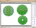
So that design is pretty well sorted, except I found out this morning when I was checking out the dimensions of the ball that I had added 10mm to the circular PCB I'd done!!!!! So As it is so remarkably tight as is now I intend to do a 2 part PCB one with the 8 555 timer circuits and their minor extra components and a second that will hold the 40 LED's and their resistors. I should mention I am doing 2 of the circuits side by side. Other than that I think it's pretty much sorted.
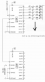
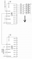
Now That circuit will show in the top half of the ball. Another circuit will show through the bottom half. This one is a pair of 4017 chips driven by a 555 timer circuit which will have a pot to change the speed. The 4017's will be joined such that the second 4017 will advance 1 LED for every 10 of the first. A 2 part design is being used again. The first will contain the 3 chips and the 1-10 count LED's with their driver transistors and resistors.
A second PCB will stack on top and this will contain the 10-100 count LED's their transistors and resistors. This design has been pulled from 2 sources. One that shows how to connect for the binary count and the other 4017 circuit showed how to connect driver transistors to the 4017. So I am using the binary type circuit with the driver transistors to be able to handle the blue LED's. I have calculated that the nearest standard value resistor is 220R to act as the current resistor. The transistors will be 2N3904 NPN's.
I am assuming I have covered the bases with this one. But could someone just check over the pic which shows my intentions and give me a yay or nay.
I should add that the voltage will be 9V.
The spec of the LED's is-
Vf 3.6V typical 4.2Max
If 25mA
I have just found that the above LED's are going to cost an arm and a leg. Actually I blacked out when I worked it out.
So I have found a bulk buy of 100 LEDs for 13 pounds sterling. They are rated at
Vf 2.8min 3.3typical 3.8max
If 30mA
For the from 4 20 circuit the current resistor will have to be 150R and for the 4017 counter circuit the nearest standard value to 190R is required. Am I still on track with this?
regards
Fenris
OK heres the thing. I have a mate who does gigs as the current Dr Who. He needed a Prop and we had arranged for me to do the circuits and a third party to do the replica prop case for my kit to go in. Unfortunately the third party is unable to complete their part so it has fallen to me to do both parts!
A compromise has been reached due to the limited time span to etch the PCB's and build the thing. The Case is a part of a hamster cage
Basically a transparent plastic ball with for 50mm dia' ports at each of the cardinal points round the equator and it splits in 2 which makes it easy to fit everything!Orac was a term used for how he wants it to look, Google Blake's 7 for that one, and to that end I have drawn up Bill Marsden's from 4 - 20 circuit as a PCB. The only other spec is that all the LED's have to be BLUE. This runs with the theme of Dr who gadgetry in the new series.
To this end the resistor values for the circuit needed changing to suit an all blue set up. Bill Kindly assisted, held my hand is more like it, me with how to work this out as, I have mentioned many times, my theory sucks!
A resistor of the value 150 or 180Ω has been calculated. This takes into account the Vf of the 555 chip and of the blue LED's I have chosen. The 2 values represent the 'typical' and 'max' Vf of the LED as per the spec sheet.
So that design is pretty well sorted, except I found out this morning when I was checking out the dimensions of the ball that I had added 10mm to the circular PCB I'd done!!!!! So As it is so remarkably tight as is now I intend to do a 2 part PCB one with the 8 555 timer circuits and their minor extra components and a second that will hold the 40 LED's and their resistors. I should mention I am doing 2 of the circuits side by side. Other than that I think it's pretty much sorted.
Now That circuit will show in the top half of the ball. Another circuit will show through the bottom half. This one is a pair of 4017 chips driven by a 555 timer circuit which will have a pot to change the speed. The 4017's will be joined such that the second 4017 will advance 1 LED for every 10 of the first. A 2 part design is being used again. The first will contain the 3 chips and the 1-10 count LED's with their driver transistors and resistors.
A second PCB will stack on top and this will contain the 10-100 count LED's their transistors and resistors. This design has been pulled from 2 sources. One that shows how to connect for the binary count and the other 4017 circuit showed how to connect driver transistors to the 4017. So I am using the binary type circuit with the driver transistors to be able to handle the blue LED's. I have calculated that the nearest standard value resistor is 220R to act as the current resistor. The transistors will be 2N3904 NPN's.
I am assuming I have covered the bases with this one. But could someone just check over the pic which shows my intentions and give me a yay or nay.
I should add that the voltage will be 9V.
The spec of the LED's is-
Vf 3.6V typical 4.2Max
If 25mA
I have just found that the above LED's are going to cost an arm and a leg. Actually I blacked out when I worked it out.
So I have found a bulk buy of 100 LEDs for 13 pounds sterling. They are rated at
Vf 2.8min 3.3typical 3.8max
If 30mA
For the from 4 20 circuit the current resistor will have to be 150R and for the 4017 counter circuit the nearest standard value to 190R is required. Am I still on track with this?
regards
Fenris
Attachments
-
 68.7 KB Views: 83
 -
 69 KB Views: 83
Last edited: