LED Lightbar 1/10 Scale

Thread Starter

Wraps2

Joined Aug 25, 2014
7
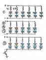
4.5in by 1.3 in, Using a combo of Super Bright White LEDs, Super Bright Blue LEDs, Red LEDs, and Yellow LEDs, with a 5 channel flasher. Designed to run off the car battery (7.2 volt - 12 volt) Custom design and produced by me. Got all the channels to work 5 (Channels of) Blue, 1 White Takedown, 1 Red Brake. However having issues with the flasher not powering the channels. Can power manually but not with flasher. If anyone can help that would be great! Attached are pictures of the Flasher and Channels.


tracecom

Joined Apr 16, 2010
3,944
Maybe someone understands your post, but I don't. First, do you have a schematic?

ETA: I found the specs for the chaser board; each channel is limited to 15mA. I suspect you are trying to exceed that. If so, you will need some drivers for the LEDs.
 
Last edited:

Thread Starter

Wraps2

Joined Aug 25, 2014
7
Maybe someone understands your post, but I don't. First, do you have a schematic?

ETA: I found the specs for the chaser board; each channel is limited to 15mA. I suspect you are trying to exceed that. If so, you will need some drivers for the LEDs.
What are Drivers?
 

tracecom

Joined Apr 16, 2010
3,944
What are Drivers?
In this case, you need a circuit that will be triggered by the 15mA output from the Cana Kit, and will switch a power source that is sufficient to light all the LEDs you have in a string. This is usually accomplished with a power transistor. You will need one such circuit for each channel that you are using from the Cana Kit.

In order to determine what power is required for each LED string, you will need to provide a schematic of the way the LEDs are wired, and the specifications for the LEDs.
 

elec_mech

Joined Nov 12, 2008
1,500
Looks like you're using this Canakit.

As tracecom mentioned, sounds like you're pulling more current from the Canakit than it can provide and adding transistors would take care of this. Personally, I like the ULN2004 as it does not require additional resistors to hook up. An example is shown below. This is not a complete schematic nor is it guaranteed to work. You need to provide us with a schematic showing how you've connected everything and what the forward voltage and current rating of each LED is. The ULN2004 will handle up to 50VDC and 500mA per channel, though I wouldn't push it that far.
 

Attachments

Thread Starter

Wraps2

Joined Aug 25, 2014
7
In this case, you need a circuit that will be triggered by the 15mA output from the Cana Kit, and will switch a power source that is sufficient to light all the LEDs you have in a string. This is usually accomplished with a power transistor. You will need one such circuit for each channel that you are using from the Cana Kit.

In order to determine what power is required for each LED string, you will need to provide a schematic of the way the LEDs are wired, and the specifications for the LEDs.
Each LED has its own resistor solder to it, the LEDs are as follows:
Yellow:
Forward Voltage: 2.0~2.2
Res 180Ω for 5V, 510Ω for 12V
maximum current is 20 mA continuous, and 50 mA peak
Blue:
Forward voltage: 3.0 to 3.4
maximum current is 20 mA continuous, and 50 mA peak
http://www.parts-express.com/super-...-kit-with-voltage-dropping-resistors--073-017

Pattern 1:
Yellow:1
Blue:11

Pattern 2:
Yellow:2
Blue:8

Pattern 3:
Yellow:2
Blue:10

Pattern 4:
Yellow:2
Blue:8

Pattern 5:
Yellow:2
Blue:8

Reds and Whites are own channels that will not flash just solid on.
 

Thread Starter

Wraps2

Joined Aug 25, 2014
7
In this case, you need a circuit that will be triggered by the 15mA output from the Cana Kit, and will switch a power source that is sufficient to light all the LEDs you have in a string. This is usually accomplished with a power transistor. You will need one such circuit for each channel that you are using from the Cana Kit.

In order to determine what power is required for each LED string, you will need to provide a schematic of the way the LEDs are wired, and the specifications for the LEDs.
Would a small relay work? like what are used in cars?
 

Thread Starter

Wraps2

Joined Aug 25, 2014
7
Looks like you're using this Canakit.

As tracecom mentioned, sounds like you're pulling more current from the Canakit than it can provide and adding transistors would take care of this. Personally, I like the ULN2004 as it does not require additional resistors to hook up. An example is shown below. This is not a complete schematic nor is it guaranteed to work. You need to provide us with a schematic showing how you've connected everything and what the forward voltage and current rating of each LED is. The ULN2004 will handle up to 50VDC and 500mA per channel, though I wouldn't push it that far.
Yup that is the one, What would a complete circuit look like?
 

elec_mech

Joined Nov 12, 2008
1,500
What would a complete circuit look like?
As I understand it, you've connected a resistor to each and every LED and wired them in parallel. If this is correct, then the schematic below should work. You'll need to trace the leads going from the 4017 to the red LED's on the circuit board then wire them to the ULN2004. Be sure to remove the LED's or resistors on the circuit board.

A few things worth mentioning:

Assuming you've selected your resistors so your LED's run from 12VDC, the brightness will be considerably lower at lower voltages, especially at 7.2V.

If you want the LED's to always be at the same brightness AND you need the circuit to run from 7.2-12VDC, then consider adding a voltage regulator such as the 7805. The regulator will accept 7.2-12V and always output 5VDC. You should then use a ULN2003 in place of the ULN2004 and replace the 12V resistors with 5V resistors. This will allow the LED's to maintain the same brightness no matter which battery voltage you use.

This is configuration will consume a lot of current and deplete your overall battery run time. You could make this a lot more efficient by putting some LED's in series, however, this is only worth considering if you supply the circuit with a specific, unchanging voltage. 12VDC would be ideal. If you need the ability to use different battery voltages, then don't worry about this.
 

Attachments

Thread Starter

Wraps2

Joined Aug 25, 2014
7
As I understand it, you've connected a resistor to each and every LED and wired them in parallel. If this is correct, then the schematic below should work. You'll need to trace the leads going from the 4017 to the red LED's on the circuit board then wire them to the ULN2004. Be sure to remove the LED's or resistors on the circuit board.

A few things worth mentioning:

Assuming you've selected your resistors so your LED's run from 12VDC, the brightness will be considerably lower at lower voltages, especially at 7.2V.

If you want the LED's to always be at the same brightness AND you need the circuit to run from 7.2-12VDC, then consider adding a voltage regulator such as the 7805. The regulator will accept 7.2-12V and always output 5VDC. You should then use a ULN2003 in place of the ULN2004 and replace the 12V resistors with 5V resistors. This will allow the LED's to maintain the same brightness no matter which battery voltage you use.

This is configuration will consume a lot of current and deplete your overall battery run time. You could make this a lot more efficient by putting some LED's in series, however, this is only worth considering if you supply the circuit with a specific, unchanging voltage. 12VDC would be ideal. If you need the ability to use different battery voltages, then don't worry about this.
Thank you so much!! When I upgrade the car to LiPo it will be a constant volage of around 7.2volts
 
Last edited:

Bernard

Joined Aug 7, 2008
5,784
Is there any reason that two LEDs cannot be connected in series, with a R, which would cut the 1 A drain down to 500 mA?
I would check Vf of all LEDs & put them in piles with dif V of 1/10 V.
 

elec_mech

Joined Nov 12, 2008
1,500
Is there any reason that two LEDs cannot be connected in series, with a R, which would cut the 1 A drain down to 500 mA?
Since the OP will ultimately use a 7.2V battery and the blue LED's could potentially need 3.4V each, there's a risk of not getting enough power to the LED's once the battery starts to drain beyond a certain point. 3.4 x 2 = 6.8V gives us 0.4V drop across the resistor which is a bit tight once the battery voltage goes down.

If, however, the OP can confirm the voltage drop across all blue LED's is close to 3.0V, then: 3 x 2 = 6V and 7.2-6 = 1.2V which is good enough for a selecting an appropriate resistor. The LED's will dim some as the battery drains, but I imagine they'll still be plenty bright at whatever the cutoff voltage to the motor is.

OP, could you test say ten of the blue LED's and measure the voltage across their leads at a constant 20mA draw? As Benard mentioned, we may be able to suggest a different wiring method which will reduce the number of resistors and power draw by about half. This will increase your battery run time considerably.
 

Bernard

Joined Aug 7, 2008
5,784
Here is a layout for series parallel LED circuit. Also simple LED Vf tester. Where a blue LED is shown, use two red LEDs in series to test blue LEDs. If DUT, device under test, is reversed, the red LEDs stay lit, if correct polarity, blue lights & Vf can be read with V meter. I tape two paper clips to edge of bench with just enough space between them for LED leads to fit & connect all together with clip leads.
 

Attachments

Top