LED help

Thread Starter

Thedax

Joined Oct 22, 2025
148
Hi Guys
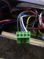
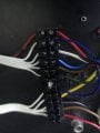
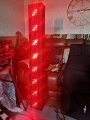
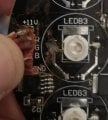
I have a question about an led module (8 in total) this is from a led stage light that runs at 12v sadly the controller board is no longer working, I would like to control them using a 24ch 512DMX decoder. The issue I have is that the decoder is 4 wire but the old module is 5 wire + R G B - Tried wiring them up with an extra negative wire directly to the 12v supply and they worked however its not right looking at the board it has 3 mosfets and 3 resistors I believe its the mosfets causing the switching. My question is can I by pass the mosfets and get the leds to work from the decoder. I've added a licture of the module/circuit board. Hope I've explained the issue thanks in advance. IMG_20251022_211206_edit_567040468265557.jpg
 

MisterBill2

Joined Jan 23, 2018
27,508
I HOPE that you still have that not working controller board, because unless it has been burned or shredded, it can be examined to discover what sort of control scheme language it used.
EVEN BETTER, it might be repairable. There are a few folks around who consider an incorrectly functioning piece as just an interesting challenge. They are the the opposite of those who would scrap and shred a $1000 console if a knob fell off.
 

Thread Starter

Thedax

Joined Oct 22, 2025
148
Thanks for the reply Sadly I don't have the board and its an unknown brand pretty limited if memory serves, So I've bought a 24ch 512 DMX box which basically does all the fancy stuff it can flash and fade strip leds, I just need to get these to work in the same way. Hoping someone understands how to wire them and can pass on the knowledge.
 

sghioto

Joined Dec 31, 2017
8,634
My question is can I by pass the mosfets and get the leds to work from the decoder.
Those mosfets are actually constant current LED drivers.
I suspect the old controller was something like this circuit below.
Each driver controls 3 LEDs of the same color wired in series and controlled by a PWM signal.
Post a photo of how you wired the connections between the 512DMX and the light fixture please?
1761186401894.png
 
Last edited:

Thread Starter

Thedax

Joined Oct 22, 2025
148
Thanks I think you have thatvspot on and explains why the lights come on but dont react to the pwm signal I have a photo of the connections plug power is the dark green followed byby R G B respectively the negative (not shown) is combined with the other connections. So do you think it will be possible to change the connections? Or am I better off just scrapping the whole unit, appreciate your input thanks.
 

Attachments

BobTPH

Joined Jun 5, 2013
11,515
Is the DMX controller putting out 3 PWM signals for R,G, and B? If so, can you verify that it can light each color separately?

There might be a mismatch in the signal levels. Or they might require pull ups or pull downs. Do you know what the signaling levels of your DMX controller are?
 

Thread Starter

Thedax

Joined Oct 22, 2025
148
Thanks for the reply, I dont know about signaling on the controller it all currently lights up with varing different displays on each led module. I searched for how much my decoder and power supply can handle and its well within the specs. Think I am very fortunate in my ignorance not to have damaged anything however it is early days. I've added some pics of the manual its 8 outputs + R- G- B- think its possible to change the pwm frequency via a menu. Sorry to be so vague I thought this was a simple upgrade just replace the circuit board lol. The last picture is them all on the same colour but the rest of the settings are either all on some on or just random. The controller can send all red all blue all green and various oter modes, thanks again for your help.
 

Attachments

sghioto

Joined Dec 31, 2017
8,634
How is the LED fixture powered? Is there an external 12 volt supply?
Can you identify the five wires in this photo?
1761227709146.png
 
Last edited:

Thread Starter

Thedax

Joined Oct 22, 2025
148
Where or

OK.
If you connect the "R" wire to 12 volts do all the RED leds turn ON?
When the 12v + is in and the negative (so none of the RGB are connected) all the lights turn on if I remove the negative and just the power and the R no lights show same with using the NEG and an R no lights.
 

panic mode

Joined Oct 10, 2011
4,978
this is what datasheet shows.
external resistor is used to set reference current.
internally two MOSFETs are forming 1:100 mirror so LED current will be 100x larger.
and to turn the LED ON/OFF, EN input is used.
END may be PWM to control the brightness.

so if the DD311 is functional, LED can turn off by
a) powering OFF
b) turning EN low (false)
c) connecting REXT low (making reference current zero and 100x0 is zero)

1761230210185.png
 

Thread Starter

Thedax

Joined Oct 22, 2025
148
Thanks for your reply but I don't really understand, I feel what I am trying to achieve is simple but alas I don't know what I doing. If I remove the chips from the circuit could I directly control the leds by wiring to the correct pin (output) the chips are one for each colour, or am I really not getting this, sorry for my lack of knowledge.
 

BobTPH

Joined Jun 5, 2013
11,515
No all are on
Connect R G and B all to ground and connect +12 and GND inputs to the 12V supply.

Hopefully that will have everything off.

The try disconnecting R G and B one at a time.

Please try this and let us know. I don’t think you will break anything unless you reverse the 12V supply.
 

Thread Starter

Thedax

Joined Oct 22, 2025
148
Sorry it took so long so I tried just connecting the RGB leds all to negative with the positive in the correct pin no lights, disconnected them one at a time still nothing when reconnected the negative all lights on even without the rgb connected at all, not sure what else I can try. The Dmx box I believe uses the RGB leds as the negative connections as it works very well andcas it should with led strip lights (tested to make sure the box 1 wasn't faulty and 2 I hadn't damaged it in my ignorance. Any other suggestions???
 

sghioto

Joined Dec 31, 2017
8,634
You need to connect 12 volt power to the fixture including the negative side of the supply.
Then connect each RGB to negative and see if they turn OFF.
 

BobTPH

Joined Jun 5, 2013
11,515
Yes, connect the +12V and negative from the power supply and leave them comnected. They are the power to the board and must be connected always.

Then you can play with the RGB.

Connect them all to ground. We think the lights will be off. Next, remove one from ground and connect to to 12V. We think that color should come on full brightness.

Please do this and let us know what it does.
 
Top