LED Dimmer using a 5-6ohm Rheostat?

Ed Thiessen

Joined Feb 13, 2018
6
The j-fet source is at the bottom of the symbol. The mosfet source is at the top of the symbol.
The j-fet is n-channel and the mosfet is p-channel. The work kind of like an npn and a pnp except their gates are very different, the logic is the same.
The voltage at the bottom of the j-fet must change as you move the dimmer.
The 10 k resistors just center everything for the benefit of the op-amp working in the center of the voltage supply.

Hello #12 measured the voltage change while varying the dimmer pot on my prototype. The voltage at - or pin two of the 1st opamp does not vary much 6.5 to 6.45 volts. I assume Vcc is the battery voltage. I measure 13 volts on the battery. How does one get Vcc -10% at position "I" on this circuit? Thanks Ed
 

Ed Thiessen

Joined Feb 13, 2018
6
Hello # 12 in this current configuration the voltage at S on the JFet is always around 9.5 volts and lights are off. When I disconnect the JFet from the 4.3 k resistors the voltage going to 2nd op amp dropped to 4.2 volts and the lights came on, so it seams like the back have of the circuit is ok. I have a 390 Ohm resistor in series with the 0 to 4 ohm dimmer control. Maybe I need to change that?
 

wayneh

Joined Sep 9, 2010
18,127
I have a 390 Ohm resistor in series with the 0 to 4 ohm dimmer control. Maybe I need to change that?
Probably, the control is only changing the total series resistance by 1%.

But before we speculate, are we working off a schematic? Sorry if I missed it.
 

Ed Thiessen

Joined Feb 13, 2018
6
Probably, the control is only changing the total series resistance by 1%.

But before we speculate, are we working off a schematic? Sorry if I missed it.

Hello Wayneh

Am working off @#12 ‘s latest schematic in the old thread. ( thread 27). He mentions that fixed resistor should be 99 x (thread 36) the dimmer pot and my GMC has a 0 - 4 ohm dimmer wire wound rheostat.

I think we may need to fiddle with some of this resistors to get that 1st opamp to react.


Appreciate any advice on this.
 

wayneh

Joined Sep 9, 2010
18,127
Well I'd divide and conquer. The timer and the the 2nd op-amp LM358 are controlling the brightness in response to the voltage applied to the "+" pin of the LM358. You should be able to apply your own reference voltages there and see the result. It appears designed to operate in the range of ~4-8V there.

If that's working, I'd turn my attention to getting that voltage range from turning the rheostat. I pretty-well follow what @#12 has done there but without it in from of me, it's hard to tell where you may have a problem. You mentioned a 390Ω resistor - is that instead of the 560Ω shown in the schematic?
 

wayneh

Joined Sep 9, 2010
18,127
The voltage at - or pin two of the 1st opamp does not vary much 6.5 to 6.45 volts.
I'm beginning to catch up to you. That voltage range is roughly what you'd expect, half of the battery voltage and varying ~1% full scale in response to the rheostat. But your FET is turned full "on", and that means the gate voltage is too high, or the FET is not oriented properly. Check the voltage on both pins of the first op-amp.

You may be suffering from imprecision of the 10K resistors. If they're a few percent off, you could get thrown out of range.
 

Ed Thiessen

Joined Feb 13, 2018
6
Well I'd divide and conquer. The timer and the the 2nd op-amp LM358 are controlling the brightness in response to the voltage applied to the "+" pin of the LM358. You should be able to apply your own reference voltages there and see the result. It appears designed to operate in the range of ~4-8V there.

If that's working, I'd turn my attention to getting that voltage range from turning the rheostat. I pretty-well follow what @#12 has done there but without it in from of me, it's hard to tell where you may have a problem. You mentioned a 390Ω resistor - is that instead of the 560Ω shown in the schematic?

I’ve got a Drok Buck Converter with variable output, I can use to test 2nd opamp and timer section I’ll try that out with 4 to 8 volts.

Yes. Trying a 390 in place of the 560 ohm resistor
 

#12

Joined Nov 30, 2010
18,224
Hello # 12 in this current configuration the voltage at S on the JFet is always around 9.5 volts and lights are off. When I disconnect the JFet from the 4.3 k resistors the voltage going to 2nd op amp dropped to 4.2 volts and the lights came on, so it seams like the back have of the circuit is ok. I have a 390 Ohm resistor in series with the 0 to 4 ohm dimmer control. Maybe I need to change that?
You are correct about using a 390 ohm resistor. Your problem is in the first stage. Yes, the input to the op-amp only changes by about 500 millivolts, but the op-amp error rating is about 5 millivolts. It thinks 500 millivolts is a big deal. If it doesn't, something is wrong in your circuit or the op-amp is broken. I sure hope you included the 100 ohms and the zener so alternator unloading spikes don't kill the op-amp. It only takes once.
 

Thread Starter

SuperRA

Joined Jan 15, 2016
9
Hello all. I know this thread is 10years old. I feel since I'm the OP and this is the continuation of this exact project, bumping is appropriate. I fell off because I just didn't have time and all with a 2nd child newly born at the time. Now she's 10 and both kids don't demand quite as much time from me anymore. I'm refreshing my Jeep with everything I've been collecting over the years and this is one of the projects I'm ready to complete!

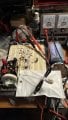
First off I want to give a big thank you to @#12 for the design. I'm sorry if it seemed like I ghosted you/this thread after post #35, but I was just in no position to devote any time to it.. Fast forward to now, I've built a prototype on a proto-board and after correcting a small mistake on the 560ohm resistor (I made mines a 1k trimpot to dial in the low setting) the circuit works! At least on a single bulb on my desk. The 0-50% ish brightness seems a little bit "flickery" but that might be because the bulb shines directly at me. It might look a bit better when viewed as the backlighting in the actual vehicle which is my next step. I should be able to try it out in the next week or so. I'll follow up with the findings and next would be to design a PCB.

@Ed Thiessen I hope you eventually got it to work, I don't know could have went wrong with your prototype, but I can verify that it works. I don't know if it matters, but the exact components/subtitutions I used were:
  • Renesas ICM7555IPAZ - timer
  • Infineon IRF9Z24NPBF - mosfet
  • TI LM358N/NOPB - OpAmp
  • Central Semi 2N5486 - JFet
 

Attachments

Thread Starter

SuperRA

Joined Jan 15, 2016
9
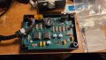
I had a PCB made from the schematic. I learned how to use Eagle and had it spit out a PCB design. I sent the files out to JLCPCB and I've got a bunch of them since it was so cheap. Shipping cost 3-4 times the PCB cost since its from China. I designed it to fit in a BUD CU-1470 enclosure. I didn't quite get everything right but give me some slack for my first time. The mounting holes are off, the corner clearance notches are quite big enough and I should have put larger holes in the PCB so I could solder at least 18ga wire. (the largest it will fit is 22ga) but it came out decent. I'm happy with the results.
 

Attachments

Top