LED Dimmer using a 5-6ohm Rheostat?

#12

Joined Nov 30, 2010
18,224
In general, you want to match the current consumption of your leds strings with that of the bulbs they replace.
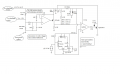
If we do that, there is no need for my circuit. Post yours. Include the sum of all currents and the correct resistance to load the lamp circuit so the existing rheostat functions like it did originally.
 

#12

Joined Nov 30, 2010
18,224
It's coming along. Haven't chosen parts or done an energy budget so I can decide how much resistance to put on the power input filter.

ps, other people are allowed to double check my schematic.;)
I actually want you to! (Sometimes I make misteaks.)
 

Attachments

Last edited:

Thread Starter

SuperRA

Joined Jan 15, 2016
7
The limiting resistor is inside the bulbs you bought. They are all pre-fabbed for use in a car. Want to check? Connect one to a car battery. If it lights up, I'm right. If it pops like a fuse, I'm wrong.:D

Really. Try it. One actual measurement is worth a dozen theories.

And yes, that diagram and the model year brings a boat load of information. If we design this good enough to pop a 5 amp fuse, we have it whipped.:cool:

It looks like that dimmer is internally connected to the high side INSIDE the headlight switch. Not accessible. You are going to have to splice in at R and I to get me the reference points I need. I will start with a variation of the first circuit I posted, a voltage to current converter, then into a resistor. The resistor converts the current into voltage and we're off to the PWM driver.:p

I still want you to unplug that switch module and measure the ohms from R to I as you spin the knob from dim to bright. That's the ONLY reference we have, so it is desperately important to know what's going on in there. The difference between 5 ohms and 6 ohms means nothing to a light bulb. It means everything to this conversion. Remember, One actual measurement is worth a dozen theories.;)
Ok I checked one of the small bulbs and it does have a resistor inside the plastic housing. Yes the dimmer is inside the headlight switch, but "inside" is a pretty loose term with this switch. I mean most of the wire wound is exposed. It may take a little surgery, but I'm sure the dimmer can be connected separately from the switch if necessary. These switches aren't too expensive, I may just buy another to do testing with. I can't exactly have this car dismantled for long periods as it is used frequently.
 

#12

Joined Nov 30, 2010
18,224
It may take a little surgery,
Just measure it. The design is already done for that part.
Still have to find a j-fet or mosfet instead of that bi-polar transistor so I can get the required output of the amplifier chip down away from its positive supply voltage. Something with about 3 volts to the pinch region or a p-mosfet with a wide gate range.
 

Attachments

wayneh

Joined Sep 9, 2010
17,496
I'm confused how the duty cycle is changed by the rheostat. Oh wait, you're not using the "output" of the 555, but rather the timing capacitor voltage waveform?
 

#12

Joined Nov 30, 2010
18,224
Your 4.2k resistors, don't you mean 4.7k (standard value)?
Umm...yep. My 40 year old reference lists 4.3K as a standard 5% value.:oops: That will probably be close enough, ~4.3K

In today's world, you can buy darn near any value of resistor but the math on that current ladder is so difficult that I burned about 6 pages of paper narrowing it down. The ultimate cure is a pot in the 100 ohm leg because whether I use 3.9k or 4.2K or 4.7K, the results are in the right range if the 100 ohm resistor changes by about 3 ohms. It's a picky little circuit, but the only difference it makes is something about whether the "dim" setting is at 16% drive time or 22% drive time...so I got it close and quit because I still don't have a measurement on the actual resistance of the dimmer in the car and I don't want to put a trim pot in a car. Too much dirt and vibration, voltage spikes and temperature changes:eek:

Here's the labels changed version.

ps, thanks for double checking me. When you burn your brain on something like this it's hard to check everything. Start up state, common mode input range, distance from the top rail, speed of the mosfet gate, energy budget...OMG!
 

Attachments

Last edited:

wayneh

Joined Sep 9, 2010
17,496
Ah yes, that explains it. I've been using E12 series resistors I got from Radio Shack years ago, and I use the nice chart here when I can't remember the values available. E12 has nothing between 3.9 and 4.7, so I knew I had never used a 4.2 or a 4.3.

I may simulate that circuit in LTspice if we get more data. Either way, some time with a breadboard would reveal a lot. I wouldn't go to a build until I had it running nicely on a breadboard.
 

#12

Joined Nov 30, 2010
18,224
I may simulate that circuit in LTspice
I would like that. The only Simulator I run is in my head.:eek:
The voltage range for Vcc is dead on...I measured a car to find out.:cool:
The dimmer in the dash will just have to be 5.8 ohms.:(
I would especially like you to examine for start-up glitches and 60 volt unloading spikes.
Be sure to put some microhenries in the wires from the dashboard to the module.;)
And check for oscillation in the first op-amp to see if I need a negative feedback capacitor (another stage of input filtering)
 

wayneh

Joined Sep 9, 2010
17,496
Hahaha, you greatly overestimate my LTspice skills. We'll see. I've been pretty absorbed in writing an app lately.
 

Thread Starter

SuperRA

Joined Jan 15, 2016
7
Well, I discovered the dimmer in the car is not functioning. I've ordered a new switch... I'll have the resistance as soon as it shows up.
 

Thread Starter

SuperRA

Joined Jan 15, 2016
7
OK, finally, the switch arrived. Man that took a long time to arrive!! I measured the resistance of the dimmer and it is 7.2ohms. I finally get to test this out. =)
 
Last edited:

#12

Joined Nov 30, 2010
18,224
The basic principle of the input divider is that the resistor labeled 560 ohms is 99 times the resistance of the dimmer. Starting with 7.2 ohms causes the 560 to become 713 ohms. That's dead between 680 ohms and 750 ohms. You can buy either one as a 1 watt resistor or just try it like it was drawn 2 weeks ago. The fat resistor only affects, "How dim is dim?"
 

Ed Thiessen

Joined Feb 13, 2018
6
The basic principle of the input divider is that the resistor labeled 560 ohms is 99 times the resistance of the dimmer. Starting with 7.2 ohms causes the 560 to become 713 ohms. That's dead between 680 ohms and 750 ohms. You can buy either one as a 1 watt resistor or just try it like it was drawn 2 weeks ago. The fat resistor only affects, "How dim is dim?"
I am building this circuit for my 1950 GMC pickup where I have installed 5 LED instrument lights. Original dimmer in this switch is 0 to 4 ohms as measured. On that basis installed a 400 ohm resistor in place of the 560. Prototype not working so far. Have triple checked the compontents and wiring is true to last posted schematic. Can you provide further explanation on this how this circuit works? Thanks
 

#12

Joined Nov 30, 2010
18,224
The first op-amp amplifies the voltage difference caused by the dimmer and uses an n-channel j-fet to create a DC voltage which changes as you move the dimmer control. That is a stable place to measure. The timer chip creates a 30.3 Hz triangle wave between 1/3 and 2/3 of the power voltage. That needs a 'scope to see. The second op-amp compares the DC level to the triangle wave and slaps a p=channel mosfet on and off as a variable pulse width chopped at 30.3 Hz. You still need to use a resistor per LED to limit the maximum LED current or use LEDs labeled for 12 volts because they have an internal resistor.
 

Ed Thiessen

Joined Feb 13, 2018
6
Thanks for the reply. At the moment the prototype I’ve built is not working. The LEDs always full on. As for my truck I have upgraded to a 12 v system with 12 v LEDs.

LED spec sheet:
Current draw: 30 mA
Operating voltage: 9 - 15 VDC
Total power consumption: 0.4 Watts

I measure the voltage at the j-fet and it’s a constant 9.4 volts. It doesn’t vary. Battery is 13.0 vdc. Dimmer switch ass’y is brand new.

Can here the 555 buzzing on my am radio when circuit is on.

I am a bit confused with the j-fet & mosfet. Would you kindly add G,S & D to the schematic for me

I hope you can assist me on this. Thanks Ed
 

#12

Joined Nov 30, 2010
18,224
The j-fet source is at the bottom of the symbol. The mosfet source is at the top of the symbol.
The j-fet is n-channel and the mosfet is p-channel. The work kind of like an npn and a pnp except their gates are very different, the logic is the same.
The voltage at the bottom of the j-fet must change as you move the dimmer.
The 10 k resistors just center everything for the benefit of the op-amp working in the center of the voltage supply.
 
Top