Facebook
 Google
 GitHub
 Linkedin
Hello,
I hope everyone is doing well.
I'll start right off with I only have the dimmest grasp of what I am doing. Although what I want to do seems simple, I'm not sure I know how to do it. I do believe I come to the right place to get the help I need") So, let's get started, shall we?
So, let's get started, shall we?
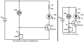
I am looking to build a simple LDR darkness sensor. I would like to use a 9V battery to light up some LED lights. Simple, right? I even have a YouTube video showing me how to do it. Couldn't be easier, right? Well, here is my problem: I am not using the same light in the video so I do not know what value resistor(s) I need. Back in the gold 'ol days I could have run down to the local Radio Shack, bought a pile of resistors and just kept plugging them in until it works. However, this is the era of online-everything and I don't have that luxury anymore.
I mean, sure, if I knew the math behind basic electronics, this would be a breeze. However, I don't so, here I am...
So, enough with that. The link to the video containing the circuit I am looking to build. There is also a link to the lights I am using. I would like to use 3 or 6 of the lights from the string.
What I would like to know is what value resistors(s) do I need?
Thank you for your time and have a great day.
Circuit:
Lights:
https://www.amazon.com/gp/product/B00WQFP3AO
I hope everyone is doing well.
I'll start right off with I only have the dimmest grasp of what I am doing. Although what I want to do seems simple, I'm not sure I know how to do it. I do believe I come to the right place to get the help I need
So, let's get started, shall we?I am looking to build a simple LDR darkness sensor. I would like to use a 9V battery to light up some LED lights. Simple, right? I even have a YouTube video showing me how to do it. Couldn't be easier, right? Well, here is my problem: I am not using the same light in the video so I do not know what value resistor(s) I need. Back in the gold 'ol days I could have run down to the local Radio Shack, bought a pile of resistors and just kept plugging them in until it works. However, this is the era of online-everything and I don't have that luxury anymore.
I mean, sure, if I knew the math behind basic electronics, this would be a breeze. However, I don't so, here I am...
So, enough with that. The link to the video containing the circuit I am looking to build. There is also a link to the lights I am using. I would like to use 3 or 6 of the lights from the string.
What I would like to know is what value resistors(s) do I need?
Thank you for your time and have a great day.
Circuit:
Lights:
https://www.amazon.com/gp/product/B00WQFP3AO