LC simulation in pSpice

Thread Starter

lcspow

Joined Mar 2, 2017
2
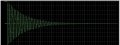
Hi everyone! I was trying to start knowing pspice by simulating a simple LC circuit (just a capacitance and an inductor with 5v and 0A as initial conditions) and checking the pure sinuisoid it should generate. But, i don't know why, the response I get is that of a RLC circuit (so it's modulated by a decrescent exponential). Does anybody know why? I'm using Orcad Schematic. I didn't find properly documentation about that on the internet.
 

Attachments

ericgibbs

Joined Jan 29, 2010
21,439
hi Ics,
A couple of reasons for the exponential decay is due to any resistance within the Inductor also some of the magnetic field is radiated away from the inductor, as per the radio transmission principle.
Not all the magnetic field collapses back into the inductor winding as an induced voltage.
E
 

MrAl

Joined Jun 17, 2014
13,702
Hi,

Also, in many simulators there is a 'default' value or set of values of maximum resistance such as a parallel resistance for the capacitor and there could be a default low value resistance for the inductor series resistance. If so, one or more of these will eat up some energy each cycle and thus you'll see a decreasing exponential instead of an ideal sine wave oscillator (which is what you get with a pure L and C and some initial energy input). Depending on what these default values are the exponential could be on a long time scale so you'll know.

You might have to go into one of the menus to set the default values.
 

Thread Starter

lcspow

Joined Mar 2, 2017
2
Thank you all for your answers! Do you know if is there an inductor model in spice which is completely ideal?
 

Alec_t

Joined Sep 17, 2013
15,117
Can't speak for Orcad, but in LTspice you can right-click the inductor symbol and set the series resistance to, for example, 1e-90 or some other close-to-ideal value. The default value is 1mΩ.
 
Top