LC Choke filter not producing desired output :(

Thread Starter

TheticVoyage630

Joined Sep 15, 2024
25
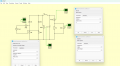
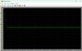
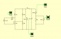
Hey guys, so im an undergrad in electrical and electronics engineering and i was trying to create this power converter that connects to AC Mains of 220V 50hz and outputs a DC Voltage of 200V using a Full wave rectifier and a choke filter using an R load of 10ohm. I referred to the internet to find the design equations for the choke filter, but the values i calculatedfor the inductor and capacitor are not producing the given output of 200V at the load. The ripple is too very high. Please help me and tell me where im going wrong.. I used the critical inductance of 10.6mh and the capacitor value of 3.75e-3. I ran the simulation in plecs and this is the output im getting. The formulas i used for Lc= R/3w0 ; and C was calculated basd on the ripple factor formula Vrf=1/(6sqrt2w0^2LC). Please help me out and tell me where im going wrong with the understanding of the circuit. Help is very much appreciated.
 

Attachments

Thread Starter

TheticVoyage630

Joined Sep 15, 2024
25
3% of its original value (325V peak-to-peak) or 3% of the DC value?
Im very new to this so im not sure i understand your question, but i will try to reply to the most of my understanding, i apologise for my ignorance in the subject, i want the ripple to be reduced to 3% to the peak value. I have watched a few videos trying to understand the LC Circuit and i think this 200V is the DC Component of the rectified ac input (2Vm/pi).
 

Ian0

Joined Aug 7, 2020
13,097
You can do some in-depth analysis to work it out, but the inductance of power inductors is not very accurate, ±10% at best, so this gets to a reasonably accurate answer more quickly.

So you want to reduce the ripple by a factor of 33, which is 20.log(33) dB which is 29.5dB.
A LC filter is a second order filter so that it rolls of at 12dB/octave, and attenuates by 3dB at the "cutoff" frequency.
So the cutoff frequency needs to be 2.2 octaves below the ripple frequency.
2.2 octaves is 2^(2.2) or 4.6, so you need a cutoff frequency of 100Hz/4.6 or 22Hz

L= √2.R/(2πf) and C=1/(√2Rπf)

which gives L=102mH.

102mH at 22A? You'll not be able to lift it on your own and it will cost a fortune!
 

schmitt trigger

Joined Jul 12, 2010
2,027
Inductor input DC power supplies have been around since the 1920s. Otto Schade from Bell Labs created a white paper and some plots which indicate the ripple, regulation and Vsupp/Vout ratio based on load resistance, series resistance, inductance and capacitance, for a given operating frequency.
There is a critical minimum inductance, a function of all the other parameters, which must be met, to prevent the inductor current becoming discontinuous.
If you can find a copy of the ARRL handbook, it has a chapter which explains this very clearly. I have my 1993 copy and treasure it as gold.
 

Thread Starter

TheticVoyage630

Joined Sep 15, 2024
25
You can do some in-depth analysis to work it out, but the inductance of power inductors is not very accurate, ±10% at best, so this gets to a reasonably accurate answer more quickly.

So you want to reduce the ripple by a factor of 33, which is 20.log(33) dB which is 29.5dB.
A LC filter is a second order filter so that it rolls of at 12dB/octave, and attenuates by 3dB at the "cutoff" frequency.
So the cutoff frequency needs to be 2.2 octaves below the ripple frequency.
2.2 octaves is 2^(2.2) or 4.6, so you need a cutoff frequency of 100Hz/4.6 or 22Hz

L= √2.R/(2πf) and C=1/(√2Rπf)

which gives L=102mH.

102mH at 22A? You'll not be able to lift it on your own and it will cost a fortune!
Im sorry but i dont understadn what you wrote :( , could you tell me how you are combining control systems to this analog circuit? please it would be of great help
 

Thread Starter

TheticVoyage630

Joined Sep 15, 2024
25
Increasing the capacitance to 7mF gives a ripple of about 9.3Vpp.
Is that what you want?

View attachment 331664
thank you for helping, i want the ripple to be as minimum as possible, and im getting a sudden surge in the voltage in the starting of the simulation before it settles down (i believe it is called peak overshoot). Idk how to fix that..and the values i get using the equations are not necessarily working.. :(
 

Ian0

Joined Aug 7, 2020
13,097
Im sorry but i dont understadn what you wrote :( , could you tell me how you are combining control systems to this analog circuit? please it would be of great help
1. Work out the attenuation required at the frequency in question (100Hz)
2. Take the frequency response graph of a 2nd order filter.
3. Find the point where that graph gives the attenuation required.
4. Work back from there to get the cut-off frequency of the filter.
5. Design the filter for the cut-off frequency required,

The filter designed is critically damped, so that it does not overshoot. That generally requires a larger inductor and smaller capacitor than one which would overshoot.
 

crutschow

Joined Mar 14, 2008
38,316
i want the ripple to be as minimum as possible
The minimum is zero with infinite size resistors and capacitors.
For actual circuits you need to specify the maximum you can live with for reasonable size and cost components.
im getting a sudden surge in the voltage in the starting of the simulation before it settles down (i believe it is called peak overshoot).
Yes, it's from the undamped resonant LC tank frequency.
This is generates a very high inductor current during startup time which then causes the voltage overshoot.

To eliminate that, you can use a current surge limiter at the input.
This can be a negative coefficient thermistor (examples), or a series resistor switched in during startup by a time-delay relay.

Below is the LTspice sim of the circuit showing the output voltage with this current surge limiter (yellow trace) which goes from 5Ω cold to 0.03Ω (top trace shows resistance), and with the limiter shorted (green trace).
The actual limiter has a 194s time-constant so will take longer to reach its minimum resistance than shown, but since the resistance will be a steep exponential function with time, it should get below an ohm in just a few seconds.

(Sorry, I can't help with the equation problems).

1726497117563.png
 
Last edited:

MisterBill2

Joined Jan 23, 2018
27,159
The impressive thing that I see is how close the circuit looks to the output circuit of a Class "C" RF power amplifier. And certainly if it is close to resonance, either at the fundamental, or at a harmonic, the ripple will be maximized. All that is missing is the second capacitor at the input end of the inductor, used to create an impedance match to the load.

That may explain the very high ripple voltage present initially.
 

MisterBill2

Joined Jan 23, 2018
27,159
So now I am suggesting to forget using a choke input and instead using the choke between the first filter cap and the second. And I am really also wondering about the alleged benefit of a choke input filter.
If there is no benefit then don't waste time on it.
 

crutschow

Joined Mar 14, 2008
38,316
And I am really also wondering about the alleged benefit of a choke input filter.
It's not alleged.
For a load current sufficient such that the inductor is continually carrying current, the output is the average of the sinewave voltage, which reduces the peak current through the diodes.
If the voltage is provided by a transformer, this also reduces the RMS dissipation in the transformer winding resistance as compared to the high peak current from the common diode-capacitor supply (which requires the transformer to be derated to below 60% of the average DC output current).

There is a "swinging choke" designed for this use, which has a significant increase in inductance as the current goes down, so the inductor current remains continuous over a wider current range.
 
Last edited:

MisterBill2

Joined Jan 23, 2018
27,159
It's not alleged.
For a load current sufficient such that the inductor is continually carrying current, the output is the average of the sinewave voltage, which reduces the peak current through the diodes.
If the voltage is provided by a transformer, this also reduces the RMS dissipation in the transformer winding resistance as compared to the high peak current from the common diode-capacitor supply (which requires the transformer to be derated to below 60% of the average DC output current).

There is a "swinging choke" designed for this use, which has a significant increase in inductance as the current goes down, so the inductor current remains continuous over a wider current range.
OK, I can see that the collapsing field will tend to keep current flowing for a greater amount of time, a lot like in a switcher supply. As I consider that, maybe the choke input filter was the inspiration for the switcher supply.
 
Top