laser level detection component for control of trencher

Thread Starter

Oldman60

Joined Jul 2, 2019
4
Hi,

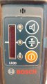
I have a small chain trencher, the kind that you would use to put in a sprinkler system. I would like to use it to put in drainage systems which require an accurate slope for the bottom of the trench. I can input a slope into a rotary level laser and I would like the depth to match. I am thinking of using a raspberry pi 4 for control, but I don't know what sensor I should use. I would like to use the same units in the readily available detectors like dewalt, johnson or leica.

Does anyone know who makes and which sensors are in the laser level detectors that commonly available?
 

Thread Starter

Oldman60

Joined Jul 2, 2019
4
Perhaps I should expand the topic. How would you detect the laser line with an accuracy necessary for some kind of control algorithm?
 

drc_567

Joined Dec 29, 2008
1,156
... One approach to your objective might be to utilize a rotary encoder to give a precise measurement of the distance from the ditch starting point to the current position of the ditching machine. Knowing this distance with some degree of precision, a stepper motor, directed by a microcontroller, something like the Arduino, maybe, would be able to activate the ditcher depth control, in a proportional manner, producing the specified drainage slope.
... Not quite sure how a laser level would fit into this scheme ... maybe it could be used to check the trench depth at certain points.
... As far as getting a practical assessment of this project, it seems like one important problem is to examine the trencher depth adjustment mechanism, and determine a means of changing the depth by means of a motor or lever.
 
Last edited:

drc_567

Joined Dec 29, 2008
1,156
... Another idea ... more of a manual approach, rather than electronic.
Set up a line of guide flags at a separation distance of 1 foot spacing from each other ... Just those small flags on the end of a length of wire. As the trenching machine passes each guide flag, lower the digging depth by 1/4". When you have completed the desired trench length, use sand or another bedding material to smooth out the slope and provide an appropriate pipe support layer.
... This process could possibly be automated ... depending on the details.
The main question to ask is how is the digging depth adjusted?
... To comply with your original idea of somehow using a beam of laser light to adjust the trench slope, you would be required to construct a vertical standing strip of photoelectric transistors or diodes, spaced closely together ... maybe 1/4" apart. Each individual sensor would have to be able to direct the depth control to change to a specific depth.
 
Last edited:

Bernard

Joined Aug 7, 2008
5,784
I might use my " TORPEDO BOY " laser level which can project a line, Set up grade stakes at each end or every 10 meters depending on trench length; mark shallow end at about 2 ft. above ground level. Shoot a level along line of stakes and mark; calculate required slope and mark. On survey rod or on trencher mount a white target with center line marked and at height to match line at start. Slanted laser line should be visable on a cloudy day or evening.
 

drc_567

Joined Dec 29, 2008
1,156
Bernard seems to have it figured out. With a white target mounted on the digging assembly, the depth of the trench will be correct so long as the laser spot is seen on the target, as the trench progresses.
 

Thread Starter

Oldman60

Joined Jul 2, 2019
4
... One approach to your objective might be to utilize a rotary encoder to give a precise measurement of the distance from the ditch starting point to the current position of the ditching machine. Knowing this distance with some degree of precision, a stepper motor, directed by a microcontroller, something like the Arduino, maybe, would be able to activate the ditcher depth control, in a proportional manner, producing the specified drainage slope.
... Not quite sure how a laser level would fit into this scheme ... maybe it could be used to check the trench depth at certain points.
... As far as getting a practical assessment of this project, it seems like one important problem is to examine the trencher depth adjustment mechanism, and determine a means of changing the depth by means of a motor or lever.
Thank you for your reply and I think it might work. I would like to have more feedback to the system. With a Rotary laser level providing continuous feedback to the height adjustment small variations in the ground or traction would not throw it off. I have attached pictures of the kind of detectors I am interested in duplicating. I just don't know how they sense the laser light.detector-40-6705.jpg LEI742685-.jpg detector-40-6705.jpg LEI742685-.jpg
... Another idea ... more of a manual approach, rather than electronic.
Set up a line of guide flags at a separation distance of 1 foot spacing from each other ... Just those small flags on the end of a length of wire. As the trenching machine passes each guide flag, lower the digging depth by 1/4". When you have completed the desired trench length, use sand or another bedding material to smooth out the slope and provide an appropriate pipe support layer.
... This process could possibly be automated ... depending on the details.
The main question to ask is how is the digging depth adjusted?
... To comply with your original idea of somehow using a beam of laser light to adjust the trench slope, you would be required to construct a vertical standing strip of photoelectric transistors or diodes, spaced closely together ... maybe 1/4" apart. Each individual sensor would have to be able to direct the depth control to change to a specific depth.
Thanks, The depth is controlled by a hand crank mechanism. I would operate that with a motor.
 

Attachments

Thread Starter

Oldman60

Joined Jul 2, 2019
4
I might use my " TORPEDO BOY " laser level which can project a line, Set up grade stakes at each end or every 10 meters depending on trench length; mark shallow end at about 2 ft. above ground level. Shoot a level along line of stakes and mark; calculate required slope and mark. On survey rod or on trencher mount a white target with center line marked and at height to match line at start. Slanted laser line should be visable on a cloudy day or evening.

Thanks that is close to what I am thinking, but I want a photo detector to read the laser line.
 

Bernard

Joined Aug 7, 2008
5,784
How long are the trenches or if trenching in segments is allowed, what is minimum length of a segment ?
Several types of sensors were discussed in post " fast horses " by barrelracerda,1-29-10.
Suggested by @ ifixit, GSR LASER TOOLS, Apache Storm Laser Receiver
 
Last edited:

Bernard

Joined Aug 7, 2008
5,784
I thought that I had a winner with Hamamatsu S875-16R 4F photo diode, ( voltage generating, .5V max )
now replaced with S12915-16R, case size 2.7 X 15 mm. Inside it works great, ambient light .1 V, laser .46 V.
Outside overcast sky about .36 V with a light shield .12 X 1 in deep X .75 in long. not enough separation for reliable operation. The plan was to use a comparator to trigger 2N5060 SCR , output to external control & to a humongus OR gate which with delay resets all SCRs. SCRs primarily to light LEDs for a different project.
 

Analog Ground

Joined Apr 24, 2019
460
I have a Bosch rotary laser level I use for building retaining walls. The detector looks to me like a Position Sensitive Detector or PSD. Hamamatsu Photonics is the big name in these devices but there are others. They come in one or two dimensions. My thinking is you would want the linear type but maybe tracking in two dimensions is useful in your application. Here is a link to Hamamatsu:

https://www.hamamatsu.com/us/en/product/optical-sensors/distance-position-sensor/psd/index.html

https://www.hamamatsu.com/resources/pdf/ssd/psd_techinfo_e.pdf

I have made instruments with both linear and 2D. They are fairly easy to use if you know op amp circuits. There are app notes and pre-amplifier boards available.

For some sort of tracking or automated system, I think keeping the beam on the detector is the challenge or searching to find it when it goes off the detector. Interesting project. Good luck!

https://www.boschtools.com/us/en/bo...MI_fO4icGj4wIV1ODICh0VZABFEAAYAiAAEgL7VPD_BwE
 
Last edited:

Analog Ground

Joined Apr 24, 2019
460
Correction to my post #11. I took a better look at the Bosch detector in more favorable light. It is an array of square photodiodes of some type. I am still thinking they are PSD. Near the edge on the pcb the silkscreen sez D1, D2, D3, etc. Here is a pic. Any lines on the detector are an artifact of the pic. The face of each detector is blank.
 

Attachments

Analog Ground

Joined Apr 24, 2019
460
Would not a PSD require a very small dot of light to supply position data ? Chip looks like 5 mm square ?
In practice, light falling on the device is split up between the electrodes in proportion to the distance to an electrode. The whole device can be illuminated but if the "field" of light is not uniform, the signal at the electrodes will give the location of an average of the light. For example, using a linear device, put one dot of light 1 mm from electrode A and another identical dot 1 mm from electrode B. The signals from the device will indicate the illumination is in the middle. Now imagine lots of dots all over the detector. In electrical terms, think of the detector as a resistive sheet and the light produces a bunch of current sources which flow to the electrodes through the sheet. The current splits up sort of like a current source going through resistors in parallel.

Edit: One important point. The location calculation is normalized to the total amount of light. For a linear device with two electrode signals, A and B. Location is given by (A-B)/(A+B).
 
Last edited:
Correction to my post #11. I took a better look at the Bosch detector in more favorable light. It is an array of square photodiodes of some type. I am still thinking they are PSD. Near the edge on the pcb the silkscreen sez D1, D2, D3, etc. Here is a pic. Any lines on the detector are an artifact of the pic. The face of each detector is blank.
The Bosch detector has three LEDs that indicate if you are above grade, on grade or below grade.If you are above, lower the blade, if below raise it, etc. Grade detection is determined by where the laser hits the photo diode array.
In your case you would use the signals to drive the trencher level in the proper direction to achieve on grade indication.

This is the type of setup used in large scale land leveling, only more sophisticated.
 
Top