Facebook
 Google
 GitHub
 Linkedin
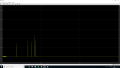
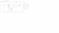
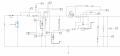
I don't really know how to title this issue. Basically, I am designing a soft-switched zero-voltage transition boost converter, I will attach a basic schematic. When running the converter and assessing the waveforms, at steady-state, I achieve the response that I desire. However, at start-up, there is a huge in-rush of current, which peaks at 1600A or so. I will include an image of the waveform also.
I am unsure what the source of this large current is. The general idea of this ZVT converter is to have a small auxiliary circuit running with a small duty cycle (10% or so) before the main switch opens, so that a small current flows through the auxiliary diode, switch, and inductor to allow the main switch to softly commutate. When I change the output capacitor to lower values, the peak value tends to decrease - could this be intefering in some way and causing the peak?
I have another issue with my design. The main switch runs at a 40% duty cycle to get 400V from a 240V input, and the auxiliary switch runs at 5-10%. However, the current in the auxiliary circuit is not much smaller than the current flowing through the main diode - which obviously is the opposite of what I want with this topology. I thought it may be because the inductor value is too small, however I used the same values that were outlined in the paper in which I discovered this topology, and at the same frequency etc.
Any help would be appreciated for these two issues.
Please see attached photos.
Thanks!
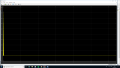
UPDATE: added a zoomed in view of the MOSFET current upon start-up. As you can see the right shape is obtained but when the switch turns ON there is a huge spike in current. Further along the waveform when steady state is reached, this no longer happens.
I am unsure what the source of this large current is. The general idea of this ZVT converter is to have a small auxiliary circuit running with a small duty cycle (10% or so) before the main switch opens, so that a small current flows through the auxiliary diode, switch, and inductor to allow the main switch to softly commutate. When I change the output capacitor to lower values, the peak value tends to decrease - could this be intefering in some way and causing the peak?
I have another issue with my design. The main switch runs at a 40% duty cycle to get 400V from a 240V input, and the auxiliary switch runs at 5-10%. However, the current in the auxiliary circuit is not much smaller than the current flowing through the main diode - which obviously is the opposite of what I want with this topology. I thought it may be because the inductor value is too small, however I used the same values that were outlined in the paper in which I discovered this topology, and at the same frequency etc.
Any help would be appreciated for these two issues.
Please see attached photos.
Thanks!
UPDATE: added a zoomed in view of the MOSFET current upon start-up. As you can see the right shape is obtained but when the switch turns ON there is a huge spike in current. Further along the waveform when steady state is reached, this no longer happens.
Attachments
-
 37.1 KB Views: 15
 -
 18.1 KB Views: 17
 -
 19.9 KB Views: 13
Last edited:

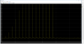
 The output capacitor also exhibits weird spikes in the first 0.015s then settles: