Facebook
 Google
 GitHub
 Linkedin
Audioguru again
- Joined Oct 21, 2019
- 6,826
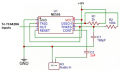
When the ICs are fairly close together then they share one 100uF capacitor for low frequencies and share one 0.1uF capacitor for high frequency decoupling.
A Li-PO and most other batteries are not rated in mA, instead they are rated in mAh which is how long a certain load current will last. A circuit does not use all of a battery's current that might be many amps for a Li-PO, the circuit uses only as much current as it needs. The preamp should use the same supply voltage as the other two ICs, not just 5V.
The LM358 preamp in the DIY project has a gain of 101 times for a low level microphone Your phone might produce 30 times more then the preamp will need much less gain to avoid severe distortion.
With the volume control on the phone turned up does your circuit work and play voices very clearly?