Facebook
 Google
 GitHub
 Linkedin
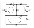
Hello guys, first of all I'm new here so if this is the wrong forum I'm sorry. I want to ask a simple question, while applying KCL, do we calculate the voltage on 5ohm as 5(I1+I3) or 5(I1-I3) ? and can somebody please give me the solution. My solution matrix is (I calculated using 5(I1+I3) because they point to same direction):
[7 0 5] [I1] [10]
[0 6 -4] [I2] =[0]
[5 -4 12] [I3] [-20]
and I calculated I1 ~= 4.79A. Is this correct? Normally I divide all cells to their individual currents but this question specifically wants us to solve this way.

[7 0 5] [I1] [10]
[0 6 -4] [I2] =[0]
[5 -4 12] [I3] [-20]
and I calculated I1 ~= 4.79A. Is this correct? Normally I divide all cells to their individual currents but this question specifically wants us to solve this way.