Jacob Shekel's method for ideal transformer

MrAl

Joined Jun 17, 2014
13,711
Hi MrAl,

Sorry for the late...
It is an interesting approach. I think your method works well. In your model, is R3 added just to model the transformer?
I see that setting R3 = 0 is easy too.
Also is there an easy way to write the matrix just by inspection?
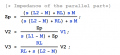
In the matrix, you replaced I1 by (V2-V3)*A/R3. How to determine of the sign here? Why not (V3-V2)*A/R3?
Hi,

You seem very clever. I say this for two reasons.
One, i was going to illustrate next with R3=0 but since you see how this can work then you can see how we can use the output impedance instead of R3.
Two, the question about the sign is a good one too i think. The answer is about what we have before and what we have after the change.
Before the change we have something like this:
a+b=-I1
and if we want to get some form of I1 on the left, we have to subtract -I1 from both sides, which looks like -(-I1) which is the same as adding I1 itself (no sign) to both sides, so we end up either way with:
a+b+I1=0

Did you say you solved the transformer problem now with the original method intended?
Or do you still require the extra resistor(s)?
 

Thread Starter

anhnha

Joined Apr 19, 2012
904
Hi MrAl,

Thanks for encouragement, actually I am a slow learner.
For the sign question, I was confused about this:


In the model, assuming the dot symbols are on top for both sides, in primary side, I1 is flowing into the dot, so if I2 is current flowing out of the dot on secondary side then I1 = A*I2 = A*(V2-V1)/R.
However, if we denote I2 as current flowing into the dot on secondary side, then I1 = -I2*A = -A*(V1-V2)/R = A*(V2-V1)/R which is same as above.

Did you say you solved the transformer problem now with the original method intended?
Or do you still require the extra resistor(s)?
I am not sure what you meant by original method. If it is Shekel's method, then I solved this and no need to to use the extra resistor.
I reassigned nodes to make it more convenient for me.

upload_2018-3-4_13-55-48.png


upload_2018-3-4_14-1-23.png

And we got the same result.

upload_2018-3-4_14-2-2.png

Your method looks neat and short too.
 

MrAl

Joined Jun 17, 2014
13,711
Hi MrAl,

Thanks for encouragement, actually I am a slow learner.
For the sign question, I was confused about this:


In the model, assuming the dot symbols are on top for both sides, in primary side, I1 is flowing into the dot, so if I2 is current flowing out of the dot on secondary side then I1 = A*I2 = A*(V2-V1)/R.
However, if we denote I2 as current flowing into the dot on secondary side, then I1 = -I2*A = -A*(V1-V2)/R = A*(V2-V1)/R which is same as above.


I am not sure what you meant by original method. If it is Shekel's method, then I solved this and no need to to use the extra resistor.
I reassigned nodes to make it more convenient for me.

View attachment 147491


View attachment 147494

And we got the same result.

View attachment 147495

Your method looks neat and short too.

Hello again,

Ok great :)

That's not really "my" method, that's just nodal analysis using the DC model of a transformer in a circuit with resistors :)

The other transformer model, the T model, is also interesting because if i remember right we can eliminate all the inductors (there's three of them) when we have an ideal transformer (k=1), and also the frequency goes away too because it becomes insensitive to frequency as well.

The other method i was talking about leads to a network without a transformer, and that comes from simply transforming all the elements on one side to the impedances reflected to the other side. I'd have to remember how to handle this though when the transformer is in a feedback circuit, and that is where the output impedance is affected by the input impedance both from the transformer and from the external circuit. I dont encounter this much anymore though.
 

Thread Starter

anhnha

Joined Apr 19, 2012
904
Hi MrAl,
I think this may be the model you are referring to. However, I don't see how inductors are eliminated for ideal transformer k = 1.

upload_2018-3-4_22-24-25.png

This book also gives many models and as in the figure d, inductors are eliminated for ideal transformer. I don't understand why figure c and d are equivalent.


upload_2018-3-4_22-32-1.png
 

MrAl

Joined Jun 17, 2014
13,711
Hi MrAl,
I think this may be the model you are referring to. However, I don't see how inductors are eliminated for ideal transformer k = 1.

View attachment 147519

This book also gives many models and as in the figure d, inductors are eliminated for ideal transformer. I don't understand why figure c and d are equivalent.


View attachment 147520
Hello again,

The inductance gets eliminated because the frequency goes out of the expressions and just leaves inductance value ratios which is not inductive anymore because Henries/Henries equals a dimensionless constant, and that happens because M=sqrt(L1*L2) when k=1.

A real simple example would be with no load, the transfer function:
Vout/Vin=s*M/(s*L1-s*M+s*M)=s*M/(s*L1)=M/L1, which is no longer frequency sensitive just the ratio of two inductor 'values' which is no longer inductive.

A second simple example is with a resistor load, and because M=sqrt(L1*L2) all the terms with frequency in it disappear.
Try it once for kicks, it's worth seeing. This is with a single resistor on the output like R2 as the output load. You can also try with a series input resistor R1, see what you get.
It makes sense though because if it was frequency sensitive it could not be ideal. But it's worth looking at...see if you can find an anomaly.
 

Thread Starter

anhnha

Joined Apr 19, 2012
904
Hi MrAl,
I have just tried the examples you suggested and see how it works now.


upload_2018-3-5_12-12-21.png

upload_2018-3-5_12-2-17.png


Next example with series resistor R1:

upload_2018-3-5_12-13-40.png


upload_2018-3-5_12-22-52.png

I see the model works well without adding any parasitic components. However the only thing I don't like much is that intead of the turn ratio N, this model is a mix of M and L1, L2. To get the final expression with N we need some substitution.
 

Attachments

Last edited:

MrAl

Joined Jun 17, 2014
13,711
Hi MrAl,
I have just tried the examples you suggested and see how it works now.


View attachment 147593

View attachment 147590


Next example with series resistor R1:

View attachment 147594


View attachment 147596

I see the model works well without adding any parasitic components. However the only thing I don't like much is that intead of the turn ratio N, this model is a mix of M and L1, L2. To get the final expression with N we need some substitution.
Hi,

So for the entire circuit the inductance does not cancel unless R1 is very small.
Same for the circuit with input resistor R1 and output load resistor R2:
(s*sqrt(L1)*sqrt(L2)*R2)/(R1*R2+s*L1*R2+s*L2*R1)

where we would again need R1 to be small to see low inductance, but it does not cancel entirely.
 
Top