Is this filter response normal ?

Thread Starter

AlexLPD

Joined Aug 22, 2010
60
Hi to you All, good lads, Im working in a project;
https://forum.allaboutcircuits.com/...n-on-a-led-amplify-stage.162725/#post-1429674

This project requires, two filters, the first a notch filter to block all the 60Hz signal, and then a Pass band filter to allow the selected frequency travel the net to pass it.

Im Making this two test of two filters that seems promising, the firs is a Tnotch filter, and the second is an Inductor and capacitor in parallel but i got this responses on the scope, and I got some certain questions;
The T notch Filter was calculated with this great tool online:
http://sim.okawa-denshi.jp/en/TwinTCRtool.php


So it gives me this values and then I proceed to assembly the circuit;
In theory with the above values the filter may be capable of -3DB of attenuation yes in practice this is not the case, I check twice the components.


Is this normal for the T notch filter?


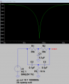
Then I assembly this other notch filter described in some diagram, its is simply an Inductor 10mH and a Capacitor of 0.1uF in parallel ;


and this is the scope response;


So the Inductor capacitor it is better, yet The signal has some distortion on it, this is due the lack of tunning of the filter?
There is some better filter for this application?

Thanks for the insights.
Kind regards.

-Alex.
 

danadak

Joined Mar 10, 2018
4,057
What is load on output of Twin T and what is the driving Z of
the generator driving the 60 Hz ? Also what is the source
of the 60 Hz into the Twin T ?

The Twin T does not look right on its connections ? Hard to see is
there a cap and 2 R's connected to ground ? Which should be just
a C an 1 R.... Although it does seem to attenuate, but has that ~ 100
Hz component in it as a 2 cycle burst synced to line (maybe its 120
Hz) ......

Regards, Dana.
 
Last edited:

SLK001

Joined Nov 29, 2011
1,549
Well, first off, 0.001H isn't 10mH, but is 1mH. Second, is you shouldn't be using a protoboard for most types of analog filter circuits. The strays are just too big and too numerous. Try building your prototypes using the air-connection method over a piece of copper clad.
 

atferrari

Joined Jan 6, 2004
4,764
It seems to me a poor contact in the protoboard, affecting both filters.

It would take few minutes soldering the whole thing in the air with short terminals. Much more reliable.
 

Thread Starter

AlexLPD

Joined Aug 22, 2010
60
What is load on output of Twin T and what is the driving Z of
the generator driving the 60 Hz ? Also what is the source
of the 60 Hz into the Twin T ?

The Twin T does not look right on its connections ? Hard to see is
there a cap and 2 R's connected to ground ? Which should be just
a C an 1 R.... Although it does seem to attenuate, but has that ~ 100
Hz component in it as a 2 cycle burst synced to line (maybe its 120
Hz) ......

Regards, Dana.
There is no load on the filters other than the scope itself.
The 60hz come from the mains, I'm using a step down transformer from 120VAC to 12VAC rms.
I will re check the connection and the over the air conectios.
 

Thread Starter

AlexLPD

Joined Aug 22, 2010
60
Well, first off, 0.001H isn't 10mH, but is 1mH. Second, is you shouldn't be using a protoboard for most types of analog filter circuits. The strays are just too big and too numerous. Try building your prototypes using the air-connection method over a piece of copper clad.
You got some serious point in here, I make a huge mistake in this value, it's I can do much more, I don't have many inductors lying around. Thanks man.
Alex
 

Thread Starter

AlexLPD

Joined Aug 22, 2010
60
Hi to you all my good fellows.

As you suggest I solder the circuit on a small piece of bread board, and re-check the values of the capacitors and the resistances,
the output of the filter, sadly remains the same:


This the ground on the central tap of the transformer.


And this is the filter output;


A bonus pic;

@SLK001 was on target with the comment on the inductor.


I was searching the web for this precise type of filters and I found this site;
http://www.nomad.ee/micros/x10filter.shtml
so this good fellow, has to do the same and filter the 110Khz from a X10 device, it ended up using a copy machine transformer with an inductance of 220uH on each side of the line and seem it worked OK from him.
So this topology can be adapted here I guees;

(this is taken from the site)
Also this is the response he plot on software;


So I got new and exiting questions;
How this filter is called?
Where I can found some information About it ?
How I can calculate or plot this responses?
In case I choose to do so, I only need the ferrite toroidal cores to adjust my circuit to some defined value?
BTW my Inductance and capacitor measurement tool come in just in time for start to search on this. Any coments on this will be also welcomed, yes, Its is not the Mastech, but for the time being.


Thanks for the insights .
-Alex.
 

Audioguru

Joined Dec 20, 2007
11,248
Your input signal is a distorted sinewave. The distortion adds the harmonic frequencies shown on your 'scope.
The wire feeding your 'scope is not shielded and it picks up all kinds of radiated interference.
Your twin-T filter works very well in a simulation:
 

Attachments

Thread Starter

AlexLPD

Joined Aug 22, 2010
60
Your input signal is a distorted sinewave. The distortion adds the harmonic frequencies shown on your 'scope.
The wire feeding your 'scope is not shielded and it picks up all kinds of radiated interference.
Your twin-T filter works very well in a simulation:
Very interesting... Im using simply mains VAC, because the filter will be used on Mains to detect a singnal, this is what I got here;


Do you think the transformer can distord the sine wave ?
What is an aternative, I got the frequency on 60Hz dead on, but how can be measure the signal distortion?

-Alex.
 

DickCappels

Joined Aug 21, 2008
10,152
If there is a core, there will be distortion. You can see it with a spectrum analyzer or the FFT function on an oscilloscope. In severe cases the waver form will appear to be distorted.

upload_2019-9-30_10-29-7.png

In this 50 Hz transformer output you can visibly see the distortion. On the right you can see the amplitudes of the odd harmonics of the 50 Hz.

upload_2019-9-30_10-31-18.png
After the distortion was corrected the waveform looks more like a sine wave and the odd harmonics are down significantly.
 
If there is a core, there will be distortion. You can see it with a spectrum analyzer or the FFT function on an oscilloscope. In severe cases the waver form will appear to be distorted.

View attachment 187101

In this 50 Hz transformer output you can visibly see the distortion. On the right you can see the amplitudes of the odd harmonics of the 50 Hz.

View attachment 187102
After the distortion was corrected the waveform looks more like a sine wave and the odd harmonics are down significantly.
How was the distortion corrected?
 

Thread Starter

AlexLPD

Joined Aug 22, 2010
60
Then
If there is a core, there will be distortion. You can see it with a spectrum analyzer or the FFT function on an oscilloscope. In severe cases the waver form will appear to be distorted.

View attachment 187101

In this 50 Hz transformer output you can visibly see the distortion. On the right you can see the amplitudes of the odd harmonics of the 50 Hz.

View attachment 187102
After the distortion was corrected the waveform looks more like a sine wave and the odd harmonics are down significantly.
Then yes, I got a distorted AC Mains, how can I make a high pass filter?
Using an OpAmp?
 

danadak

Joined Mar 10, 2018
4,057
If there is a core, there will be distortion. You can see it with a spectrum analyzer or the FFT function on an oscilloscope. In severe cases the waver form will appear to be distorted.

View attachment 187101

In this 50 Hz transformer output you can visibly see the distortion. On the right you can see the amplitudes of the odd harmonics of the 50 Hz.

View attachment 187102
After the distortion was corrected the waveform looks more like a sine wave and the odd harmonics are down significantly.
Dick, what is causing the non linear behavior here ? I always thought cores were
linear over operating range, does this mean no portion of core flux curve is linear ?

Regards, Dana.
 

DickCappels

Joined Aug 21, 2008
10,152
danadak, as the magnetizing current in the core increases a voltage drop in the primary (primary resistance x magnetizing current) increases. This results in fewer volt-turns on the core which results in a distorted waveform across the secondary. This was a power transformer, not an audio transformer so I doubt the designers paid a lot of attention to the effect.

TheElectrician, the fix was to induce negative resistance approximately equal to the resistance of the primary winding, in the linear amplifier that was driving the primary.

AlexLPD, not sure you would want a high pass filter because the distortion is in the harmonics of the mains frequency. There are plenty of opamp filter circuits in this handbook, web.mit.edu/6.101/www/reference/op_amps_everyone.pdf
 

Thread Starter

AlexLPD

Joined Aug 22, 2010
60
High pass?
Sorry I was thinking on other stuff a pass band filter, the main idea once I can fully implement the filter for 60hz, it is "dye" each one of the three phases with a distinct pulse eg.120khz, 480khz and 700khz.. and it use for distinct the correct wire from a circuit.
 
Top