Is question 31 what's going on here!

Thread Starter

TayAllen01

Joined Mar 22, 2022
11
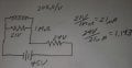
I am having trouble with a question on an electronics test. These test I'm taking only have the answers and not an explanation of how it was found. The answer for the question is B. 1.14 Meg ohms. Is that right? And how is it found with the information given. The closest answer I could come up with is 17.5 K ohms. Is there information not being provided here. Is there an understanding of this type of problem that I don't have. NO SMART ANSWERS. Please.

Thanks for your time,

Mr. TQuestion 31.jpg
 

crutschow

Joined Mar 14, 2008
34,906
Do you know how to calculate the input resistance of the 20kΩ/V meter when set to the 50V scale?

(Of course that meter is a ancient analog meter, which is seldom used anymore.)
 
Last edited:

WBahn

Joined Mar 31, 2012
30,329
It's hard to spot where you went wrong and got the answer you got when you don't show us how you got the answer you got. So that would definitely be a good starting point?

Do you know what a voltmeter's "ohms/volt" rating means? If not, or if you are just guessing, looking into that would also be a good place to explore.
 

Thread Starter

TayAllen01

Joined Mar 22, 2022
11
Do you know how to calculate the input resistance of the 20kΩ/V meter when set to the 50V scale?

(Of course that meter is a ancient analog meter, which is seldom used anymore.)
Do you know how to calculate the input resistance of the 20kΩ/V meter when set to the 50V scale?

(Of course that meter is a ancient analog meter, which is seldom used anymore.)
Yes, I think that's right. This is using an old analog meter and that's what throwing me off. No I don't know how to calculate the input resistance of 20kΩ/V set at 50V scale. I was assuming that the coil impedance was 20 K ohm's. According to the schematic the meter is hooked in series with the resistance. So then is the 21V across the meter or across the resistor. Which I'm going to call R1. If the meter then 21V divided by 20kΩ would equal the current through the circuit. Which would be 1.05mA. So then 45V -21V would be a crossed R1. That divided by 1.05mA. Would give a resistance of around 22kΩ for R1. That's not right, so then 45V -21V is across the meter coil. That divided by 20kΩ would be 1.2mA. This looks right, but when divided into 21V the resistance comes out to be 17.5kΩ. That's where I come up with my answer. But that's not right!

Normally when you take a voltage measurement across the resistor you place the meter in parallel with the resistor. if that was the case then you would have the same voltage across the meter as you would across the resistance. Both would be in parallel to become total load. You would not have two voltages 45V and 21V. The battery may be drug down to 21V. So let's start there. Assuming, which I'm doing too much of it, that the coil impedance is 20kΩ then we're back to the same formula of 21V divided by 20kΩ which gives us 1.05mA. The trouble is that it is only one of portion of the current. There is no way to tell the total amount of current being drawn from the battery. Since we have no idea what the resistance R1 really is. So this is a dead-end.

So now let's look at another way. If you look at the information of 20kΩ per volt literally. You multiply 20 kg homes by 21V to come up with 420kΩ. Well that's just silliness and it doesn't work let alone it not being right.

So you're right I need to figure out how to calculate the input resistance of a 20kΩ/V voltmeter with a 50V scale. I guess the question for Google is "How to calculate the input resistance of a 20kΩ/V meter with a 50 V scale". Accessing Google. One moment please. Accessing. Accessing. Accessing. Well one thing that stands out is that amplified voltmeters often have an input resistance of 1, 10, or 20 megohms. Not 20kΩ/V. Interesting but not a gamebreaker.

Taken from https://www.quora.com/A-meter-havin...at-is-the-reading-of-the-meter-on-a-10V-scale

To determine the reading of the meter on a 10V scale, we need to consider the voltage division between the output resistance of the circuit and the internal resistance of the meter.
Given:
- Sensitivity of the meter = 2k ohm/V
- Output resistance of the circuit = 1k ohm
- Open circuit voltage = 8V


The total resistance in the circuit when the meter is connected is the sum of the output resistance of the circuit and the internal resistance of the meter:
Total resistance = Output resistance + Internal resistance = 1k ohm + 2k ohm = 3k ohm

When the meter is connected to the circuit, it forms a voltage divider with the output resistance of the circuit. The voltage across the meter can be calculated using the voltage divider formula:

40 V_{\text{meter}} = V_{\text{out}} \times \frac{R_{\text{meter}}}{R_{\text{circuit}} + R_{\text{meter}}}41

Where:
- 40 V_{\text{meter}} 41 is the voltage across the meter
- 40 V_{\text{out}} 41 is the open circuit voltage = 8V
- 40 R_{\text{meter}} 41 is the internal resistance of the meter = 2k ohm
- 40 R_{\text{circuit}} 41 is the output resistance of the circuit = 1k ohm

Plugging in the values:
40 V_{\text{meter}} = 8 \times \frac{2}{1 + 2} = 8 \times \frac{2}{3} = \frac{16}{3} \approx 5.33V 41

Therefore, the reading of the meter on a 10V scale would be approximately 5.33V.
Given the information here Then copying the form, we can confirm that 17.5kΩ is the answer? But way does the text say difference
8V/3kΩ =2.66666mA 45V/37.5kΩ =1.2mA
2.66666mA*2=5.333333V 1.2mA*17.5kΩ=21V


I'm tired and there's definitely something missing from the instructions in this problem. The writer of this test assumed I would know certain things that he knows. And that's why I can't get the correct answer. Either that or it's a bogus question. I'm thinking it's a bogus question. If anyone out there has any ideas on what I'm doing wrong with my analysis or any information that I might be excluding including processes please leave a post. It will be most welcome. Also if there are websites work and asked this question and maybe find the correct answer please let me know if such. Until then I'm going to consider this question a messed up question and not trust any of the rest of these tests that I'm taking for practice.
 

Thread Starter

TayAllen01

Joined Mar 22, 2022
11
All information is present.
Perhaps you can show the calculations that gave you 17.5k, then we can correct the error that took you there.
Please look below
I worked it through. It is not bogus. One of the answers is the correct answer.
I went through the procedure that I use to find the answer. It's still the wrong answer though according to the book.

So you work through it and you tell me where I made my mistake? just a hint will do.
 

Thread Starter

TayAllen01

Joined Mar 22, 2022
11
It's hard to spot where you went wrong and got the answer you got when you don't show us how you got the answer you got. So that would definitely be a good starting point?

Do you know what a voltmeter's "ohms/volt" rating means? If not, or if you are just guessing, looking into that would also be a good place to explore.
I work through my logic below if you want to look. Yes I think you're right I need to figure out how to work with ohm's/volt ratings and find out what it means to apply it correctly.
 

MrChips

Joined Oct 2, 2009
31,172
The meter resistance is 20,000 Ω/V. Hence for 50V range, the meter resistance is 1MΩ.

Use algebra and write down the two equations for current for case 1 and case 2.
You know the ratio of the two currents.
Solve two simultaneous equations for R.
 

boostbuck

Joined Oct 5, 2017
574
The meter resistance is 20,000 Ω/V. Hence for 50V range, the meter resistance is 1MΩ.
This is where your error lies. If you calculate the meter resistance as MrChips describes, the rest of the exercise is a simple voltage divider with two knowns (meter resistance and voltage across it) to find unknown R.
 

Thread Starter

TayAllen01

Joined Mar 22, 2022
11
Thank you LowQCab crutschow and WBahn. It took me a long time to get the answer on the Internet. I wish you could have been a little more direct. Because it took me hours of searching. I've never used an analog meter. Not in this way.
 

Attachments

Thread Starter

TayAllen01

Joined Mar 22, 2022
11
I guess we thought the 20kΩ per volt spec for the meter resistance was reasonably self explanatory and we didn't need to spoon feed you the answer, but apparently that was not correct.
Never used in analog meter before. Very little information out there on how to use them. I've use Flukes all my life. Sorry you had to spoon feed me. I did finally get the correct answer. I can't wait for Tube questions next.
 

WBahn

Joined Mar 31, 2012
30,329
Thank you LowQCab crutschow and WBahn. It took me a long time to get the answer on the Internet. I wish you could have been a little more direct. Because it took me hours of searching. I've never used an analog meter. Not in this way.
I thought suggesting that you explore what a meter's ohms/volt rating meant was pretty direct.

If I just Google "ohms/volt" I get the following hits:

What exactly does ohms-per-volt mean and how ...

Why is analog "voltmeter sensitivity" is defined as ohm/Volt?

Voltmeter - Wikipedia

and several other relevant ones. Learning how to track down information is an extremely important skill that is only learned by having to track information down. The more you do it, the better at it you will get.
 

boostbuck

Joined Oct 5, 2017
574
I have always thought the specification of 20k ohms/volt to be in very ambiguous units. It's really an indirect way of describing the current needed to drive the meter, in this case 50uA FSD which I think is much clearer when faced with a problem requiring application of ohms law. 50uA at 50 volts FSD is very obviously 1 meg resistance.
 
Top