
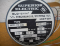
Dear Madam/Sir, I have a M091-FD-308 stepping motor from Superior Electric: (See attached picture) and I have a bipolar driver. Is the M091-FD-308 stepping motor bipolar? so that I can use my bipolar driver (LIN R256)?
Thank you, Rachid
Thank you, Rachid
Attachments
-
 2 MB Views: 8


