Facebook
 Google
 GitHub
 Linkedin
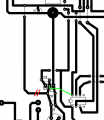
As far as the noise problem, you have the Vss(pin13) and Com(pin2) tied together.
According to an app note on these drivers, that I can't find link to right now, they put two different commons/grounds in these chips to prevent the 'noise' problem.
Pin #2 is the mosfet ground and Pin #13 is the logic circuit ground. They are to be kept separate. If you look at the circuit on page 1 of the data sheet you'll see what I mean; http://www.irf.com/product-info/datasheets/data/ir2110.pdf
The large capacitor value for the bootstrap circuit did you calculate it that large? Here is the app note for figuring the values of the bootstrap circuit; http://www.irf.com/technical-info/appnotes/an-1123.pdf By using a PWM input on the Lin only of the 2110 you can use a smaller value of bootstrap capacitor. with the Hin a steady signal and the Lin pulsing the bootstrap capacitor will keep getting recharged.
Last edited: