Facebook
 Google
 GitHub
 Linkedin
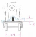
This is similar to what I had in mind, thanks.A strange tilt arrangement:
A - micro servo like Towerpro SG 50 or MG90S about 3 cm total length.
B & C- solenoid operated latches front & rear, release with power on. View attachment 102819 View attachment 102820
IR Speed Detector for model railway
- Thread starter flashman99
- Start date