Inverter problems Please help

Thread Starter

James Harris 1

Joined Mar 10, 2017
39
Then remove all the MOSFETs ( all of the ones in the small PCB) after discharging the HV.

Need to check All MOSFET's and the drivers plus the little diodes around.

Do you know how to ?
I got to go. I will be back tomorrow this time.
Hope by the time I come back some one could show you how to test them with DMM.
Or Google it.

Before testing you need to short all the pin of the MOSFET to discharge the gate capacitance.
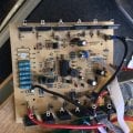
I've taken all the mosfets out of the pcb and tested them so all mosfets in pcb are now good. I'm not sure on how to test the drivers.I'm going to remove the diodes in the morning and test them. I've tested them while they are still on the board but to be sure I'll remove and test them
 

Thread Starter

James Harris 1

Joined Mar 10, 2017
39
Right all mosfets tested all diodes tested I found a broken diode so that should be in the post tomorrow finger crossed I'll receive it on Tuesday only thing left to test is the driver but I'm not sure on how to do that.
 

R!f@@

Joined Apr 2, 2009
10,004
Post the driver numbers....if you can identify them ?
I cannot the see the PCB numbering but one, which is Q57.
There are 4 drivers as Q57, Post there numbers, which is likely just transistor pairs.

How do you know the MOSFET's tested OK....I am not questioning your ability but rather like to be sure your test method is valid or not.

The broken diode is a zener or not ?
Did you break it while removing or is it shorted ?
 

Thread Starter

James Harris 1

Joined Mar 10, 2017
39
Post the driver numbers....if you can identify them ?
I cannot the see the PCB numbering but one, which is Q57.
There are 4 drivers as Q57, Post there numbers, which is likely just transistor pairs.

How do you know the MOSFET's tested OK....I am not questioning your ability but rather like to be sure your test method is valid or not.

The broken diode is a zener or not ?
Did you break it while removing or is it shorted ?
Hi the drivers numbers are mje 13003 and I used this website https://www.utm.edu/staff/leeb/mostest.htm for the mosfet test
 

R!f@@

Joined Apr 2, 2009
10,004
When putting everything back, just put one H-bridge...i.e is just 4 MOSFETs, and leave the other 8 out.
All the MOSFET's are in parallel to form a high current H-Bridge.
So just 4 ( Single MOSFET H-Bridge ) will work and is best for testing.

If 4 works, all will work if the MOSFET's are not fault or partial fault.

It is a must to check the silicon insulators for breaks and pin holes. It tends to break when you remove them.
Double checking is a must when assembling.
Or you are likely to connect a Drain to the chassis.
I always use new ones once working.
 

Thread Starter

James Harris 1

Joined Mar 10, 2017
39
Post the driver numbers....if you can identify them ?
I cannot the see the PCB numbering but one, which is Q57.
There are 4 drivers as Q57, Post there numbers, which is likely just transistor pairs.

How do you know the MOSFET's tested OK....I am not questioning your ability but rather like to be sure your test method is valid or not.

The broken diode is a zener or not ?
Did you break it while removing or is it shorted ?
Yeah zener and it was shorted out
 

Thread Starter

James Harris 1

Joined Mar 10, 2017
39
When putting everything back, just put one H-bridge...i.e is just 4 MOSFETs, and leave the other 8 out.
All the MOSFET's are in parallel to form a high current H-Bridge.
So just 4 ( Single MOSFET H-Bridge ) will work and is best for testing.

If 4 works, all will work if the MOSFET's are not fault or partial fault.

It is a must to check the silicon insulators for breaks and pin holes. It tends to break when you remove them.
Double checking is a must when assembling.
Or you are likely to connect a Drain to the chassis.
I always use new ones once working.
Ok will do thank you for the tips should I put it back together now or wait for the diode to arrive
 

Thread Starter

James Harris 1

Joined Mar 10, 2017
39
When you say just put back 4 looking at the back of the pcb they seem to be in groups of 3 so would I do 3 or a set of 3 and 1on another section
 

Thread Starter

James Harris 1

Joined Mar 10, 2017
39
So the test pass all the 4 conditions ?


That is actually a good, u know. Finding a fault.
Do you know the value ?.


Are all the same number ?
Yeah all the same number and results are drain to source
No.1 578
No.2 566
No.3 593
No.4 600
No.5 590
No.6 584
No.7 576
No.8 589
No.9 583
No.10 1
No.11 001
No.12 1
No. 13 578
No. 14 593
No.15 573
I tested the 3 new ones for good measure hence 15 mosfets instead of 12 and all mosfets with readings turn off once I shorted the pins with my finger
 

R!f@@

Joined Apr 2, 2009
10,004
Hmm ! Seems OK..

Google how test NPN transistors while I show how to Solder MOSFET's

The MJE 13003 are HV NPN Transistors. If all 4 are MJE13003, they all are NPN's.
 

R!f@@

Joined Apr 2, 2009
10,004
That would work.

But do post your DMM reading. I am attaching the MJE13003 for your reference..you can find B,C,E from it.

Picture shows the MOSFET layout
A's from 1 bridge
B's from 1 bridge
C's from 1 bridge

It does not matter what you chose to solder.
You can solder the A's, B's or C's, position MOSFET's to do an initial checking.

Good luck
 

Attachments

R!f@@

Joined Apr 2, 2009
10,004
I got to go....so for now....
Say you manage to get the output with one bridge, so please do not keep it powered for long and do not test with light loads.
Even for light loads the Boost converter draws a significant amount of current.
Even to check with a light load you need to mount the transistors to the chassis (heatsink) properly.
I can do a load test quite fast without a sink but I do not recommend this to you as you are a novice.

So, please mount it on the sink once you get the proper output with just one set of MOSFET's and do a load test with a 5W 220V light bulb first and let it run for a while.
If satisfied, solder second pair of MOSFET's and check for ouput.
and so on.

A pair of MOSET's here means 4 pieces
 

Thread Starter

James Harris 1

Joined Mar 10, 2017
39
That would work.

But do post your DMM reading. I am attaching the MJE13003 for your reference..you can find B,C,E from it.

Picture shows the MOSFET layout
A's from 1 bridge
B's from 1 bridge
C's from 1 bridge

It does not matter what you chose to solder.
You can solder the A's, B's or C's, position MOSFET's to do an initial checking.

Good luck
Ok tested the 4 mje13003 the results are on a ohm setting of 200k and still on pcb
No.1 negative: b-e 04.6 b-c 15.2 positive: b-e 04.6 b-c 15.2
No.2 negative: b-e 7.3 b-c 1 positive: b-e 06.7 b-c 94.9
No.3 negative: b-e 04.6 b-c 15.0 positive: b-e 04.6 b-c 15.0
No.4 negative: b-e 07.1 b-c 0.00 positive: b-e 07.1 b-c 0.00
 

Thread Starter

James Harris 1

Joined Mar 10, 2017
39
I got to go....so for now....
Say you manage to get the output with one bridge, so please do not keep it powered for long and do not test with light loads.
Even for light loads the Boost converter draws a significant amount of current.
Even to check with a light load you need to mount the transistors to the chassis (heatsink) properly.
I can do a load test quite fast without a sink but I do not recommend this to you as you are a novice.

So, please mount it on the sink once you get the proper output with just one set of MOSFET's and do a load test with a 5W 220V light bulb first and let it run for a while.
If satisfied, solder second pair of MOSFET's and check for ouput.
and so on.

A pair of MOSET's here means 4 pieces
Ok will do thank you so much for your help I'll post my results
 

Thread Starter

James Harris 1

Joined Mar 10, 2017
39
Right I've taken the mje13003 out of the board and retested this time in diode test mode the results are.
No.1 negative: b-e 1 b-c .001 positive: b-e 1 b-c .002
No.2 negative: b-e 1 b-c 1 positive: b-e .796 b-c .732
No.3 negative: b-e 1 b-c 1 positive: b-e .801 b-c .721
No.4 negative: b-e 1 b-c 1 positive: b-e .804 b-c .737
Am I right in thinking no.1 is dead
 

R!f@@

Joined Apr 2, 2009
10,004
Am I right in thinking no.1 is dead
You are getting better. :)
1 has a shorted BC junctions and an open BE junction.

Is this the transistor that has the diode connected ?

by the way, correct method is post #59. DMM should be in Diode check mode for checking transistors and diodes.
Disregard the test in Post #57
 
Top