I told you in post #7 what tests to do. You replied in post #9 when it had stopped working but when you got it working again in post #10 you did not do the tests.
@James Harris 1
I have repaired a couple of inverters from low voltage to poor regulation.
I can help but my time is rather limited but I can point out what to look for.
I need voltage measurements at certain points but to point that out I need to see the PCB's properly.
Your pictures are not enough and of poor quality for me to tell you anything.
This does not mean I need big file size pictures. I need good quality pictures with good lighting and no glare.
Resize them and attach them. High resolution with small file size is OK for me as my bandwidth is limited.
Just attach them as you did before.
Then if time allowed I can guide you.
I may not reply promptly but I will reply.
PS. I need to see the whole PCB from both sides.
I told you in post #7 what tests to do. You replied in post #9 when it had stopped working but when you got it working again in post #10 you did not do the tests.
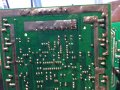
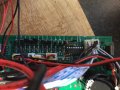
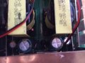
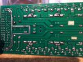
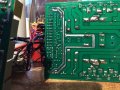
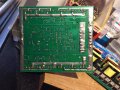
These are the 3 images I found useful.
See how you took the backside of the PCB nicely, now I need the component side the same way. Good lighting too. I do not need multiple pictures. One picture of the whole PCB
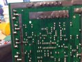
These are the 3 images I found useful.
See how you took the backside of the PCB nicely, now I need the component side the same way. Good lighting too. I do not need multiple pictures. One picture of the whole PCB
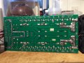
It looks like it is not just one side of the H bridge not working. I was expecting to see a DC reading of about 130 volts. (About the same reading that your meter gave set to AC) It looks like there is some output from both states of the H bridge but they are not the same. (Hence the DC offset.)
It looks like it is not just one side of the H bridge not working. I was expecting to see a DC reading of about 130 volts. (About the same reading that your meter gave set to AC) It looks like there is some output from both states of the H bridge but they are not the same. (Hence the DC offset.)
Without load
Not sure what you mean about limited output ac im getting 130v ac at the output if that helps or at the out put I'm getting -85v dc also at the output socket
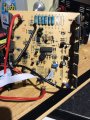
Then remove all the MOSFETs ( all of the ones in the small PCB) after discharging the HV.
Need to check All MOSFET's and the drivers plus the little diodes around.
Do you know how to ?
I got to go. I will be back tomorrow this time.
Hope by the time I come back some one could show you how to test them with DMM.
Or Google it.
Before testing you need to short all the pin of the MOSFET to discharge the gate capacitance.
Then remove all the MOSFETs after discharging the HV,
Need to check All MOSFET's and the drivers plus the little diodes around.
Do you know how to ?
I got to go. I will be back tomorrow this time.
Hope by the time I come back some one could show you how to test them with DMM.
Or Google it.
Before testing you need to short all the pin of the MOSFET to discharge the gate capacitance.
 Facebook
 Google
 GitHub
 Linkedin