inversion of coil secundary capacitive picked up signal

Thread Starter

patpin

Joined Sep 15, 2012
405
Hello,Can anyone help me on the way... I would like to invert an analog signal received from the secundary of a car ignition coil, which I picked up with a capacitive probe 1000:1 described here ( http://www.lotuselan.net/forums/download/file.php?id=9946) .
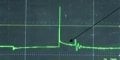
The resulting signal has peaks up to 40V (40 KV on secundary/1000), but the wave shape should be some thing like below: "oscillo secundary normal".
In fact (with the probes described above) I get the mirrored image (on a horizontal axe). This is rather difficult to interprete since textbooks on the subject always display the signal with the largest peak goiing upward; I was thinking of a 1:1 transformer. Any one has some experience with those things?
 

Attachments

Thread Starter

patpin

Joined Sep 15, 2012
405
Doesn't the bitscope have a polarity inversion option for the input signal?
Haven't found that on it. http://bitscope.com/product/BS05/?p=specs

BTW I forgot to mention that I use a scope Probe 10:1 after the 1000:1 capacitive pickup probe described in #1, since the Bitscope inputs can only be +10V->-7 or so.
I v got an old modem transfo (probably 1:1; ohmic 156 ohm both windings). Could I do it with that? And how to connect so that the wave shape doesnt alter (beside it's mirrored).
 

crutschow

Joined Mar 14, 2008
34,910
Depending upon the frequency components of the signal, I think the transformer will likely significantly distort the signal wave shape.
Your best bet might just be a high frequency op amp configured for a inverting gain of -1.
What is the horizontal sweep speed of the oscilloscope display in the first post?
 

Thread Starter

patpin

Joined Sep 15, 2012
405
Depending upon the frequency components of the signal, I think the transformer will likely significantly distort the signal wave shape.
Your best bet might just be a high frequency op amp configured for a inverting gain of -1.
What is the horizontal sweep speed of the oscilloscope display in the first post?
Not my own capture but my best guess is 8ms/div.
 

Thread Starter

patpin

Joined Sep 15, 2012
405
Not my own capture but my best guess is 8ms/div.
Your best bet might just be a high frequency op amp configured for a inverting gain of -1.
Which one would you use. I have a LM358 here. Is the input impedance high enough to 'NOT distort' the signal and how would you dimension it? Is the negative goiing part of the signal a problem? I dont want to loose signal quality.
 

crutschow

Joined Mar 14, 2008
34,910
The LM358 has a typical gain-bandwidth around 1MHz so the frequency response at a gain of -1 would be about half that, which probably will be sufficient if the sweep speed of that posted display is only 8ms/div (which is an odd number since usually oscilloscope sweep speeds are in a 1, 2, 5, 10 sequence).

Actually, considering your use of a 10:1 probe, you could use a 10 MegΩ input resistor and a 1 MegΩ feedback resistor to run the op amp at an inverting gain of -0.1, giving you the same output signal level as with the probe.
That will also increase the bandwidth to near 1 MHz.

If you want both positive and negative signal transitions then you either need to capacitively couple the input and output, and bias the op amp positive input at 1/2 the supply voltage with a resistive divider, or use a dual (plus and minus) supply voltage.
 

Thread Starter

patpin

Joined Sep 15, 2012
405
The LM358 has a typical gain-bandwidth around 1MHz so the frequency response at a gain of -1 would be about half that, which probably will be sufficient if the sweep speed of that posted display is only 8ms/div (which is an odd number since usually oscilloscope sweep speeds are in a 1, 2, 5, 10 sequence).

Actually, considering your use of a 10:1 probe, you could use a 10 MegΩ input resistor and a 1 MegΩ feedback resistor to run the op amp at an inverting gain of -0.1, giving you the same output signal level as with the probe.
That will also increase the bandwidth to near 1 MHz.

If you want both positive and negative signal transitions then you either need to capacitively couple the input and output, and bias the op amp positive input at 1/2 the supply voltage with a resistive divider, or use a dual (plus and minus) supply voltage.
Thanks for yr answer.
It (time/div) was an estimation. To be more accurate: the horizontal part after the large positive peak (spark line ) is typically 1.3 msec before the oscillations start.
As for the diagram for the opamp: do U mean some thing like this http://www.analog.com/library/analogDialogue/archives/35-02/avoiding/index.html . Which one of the described diagrams would U prefer. I would consider diagram 3? But how to reduce the gain to -0.1. I would try to sim it with LTspice
 
Last edited:

crutschow

Joined Mar 14, 2008
34,910
Yes, Figure 3 should work.
As I stated, you can make R1 = 10 MegΩ and R2 = 1 MegΩ to give a high input impedance with a gain of -0.1.
1μF for C2, and Cout should be sufficient.
You don't need C1 since your signal is already capacitively coupled.
 

Thread Starter

patpin

Joined Sep 15, 2012
405
Yes, Figure 3 should work.
As I stated, you can make R1 = 10 MegΩ and R2 = 1 MegΩ to give a high input impedance with a gain of -0.1.
1μF for C2, and Cout should be sufficient.
You don't need C1 since your signal is already capacitively coupled.
Many thanks for info. Can C2 and Cout be polarized?
 

crutschow

Joined Mar 14, 2008
34,910
Many thanks for info. Can C2 and Cout be polarized?
Yes.
C2 positive side to the junction of Ra and Rb, and Cout positive to the output of the op amp.

Note that you will need a single supply voltage of at least 10V to avoid clipping the signal.
 

Thread Starter

patpin

Joined Sep 15, 2012
405
after changing voltage to 12v and after changing the PWL in order to check if I still have the oscillations at the end of the signal... please have a look. I miss the oscill. in the output..;HV input protection met TVS en opampLM358 capacitive03 zonder TVS.jpg
 

Thread Starter

patpin

Joined Sep 15, 2012
405
a more realistic PWL gives following output. I miss the small oscillations and the voltage sinking slowly after 4.0ms (this line should rise on the mirroring output). I think the capacitive probe is the problem and off coarse the decoupling on the output too. Is there a solution?HV input protection met TVS en opampLM358 capacitive04 zonder TVS ander PWL.jpg
 
Last edited:

crutschow

Joined Mar 14, 2008
34,910
What is the purpose of the 1 meg resistor to ground at the input?
You shouldn't need that with the 10 meg input of the op amp.

Just noticed a newbie error that is common when first using Spice.
You have R5 as 10m which is interpreted as 10 milliohm by Spice.
It should be 10meg.
 

Thread Starter

patpin

Joined Sep 15, 2012
405
What is the purpose of the 1 meg resistor to ground at the input?
You shouldn't need that with the 10 meg input of the op amp.

Just noticed a newbie error that is common when first using Spice.
You have R5 as 10m which is interpreted as 10 milliohm by Spice.
It should be 10meg.
Indeed I have very little experience with LTSPICE. Thanks for mentioning the error. The output is now perfect !!!!! Many thanks for yr help!!!
in the article ref.d in #1 on page 5 they explain the R as "

A second capacitor of about l000pF should be connected as shown. The capacitive divider thus formed divides the
input signal by about 1000:1 thus reducing the input signal to a workable 3 - 20 volts. A 1M resistor should be

connected across the l000pF capacitor to provide a dc load. "
 
Last edited:
Top