Intermittent Battery Float Charger

floomdoggle

Joined Sep 1, 2008
217
As always, please take my post with a grain of salt. I had heard if you put the positive and the negative from your charger on different batteries, then jump to the others, you will have a more even charging .
Sort of like this: bat1 pos to bat2 pos bat3 pos to bat4 pos, bat1neg to bat3 neg bat2neg to bat4 neg. Place the charger at bat2 pos and bat3 pos, and bat1 neg and bat4 neg.
I have no idea why this works, but somehow it does. Check out otherpower.com for a better answer.
Dan
 

SgtWookie

Joined Jul 17, 2007
22,230
As always, please take my post with a grain of salt. I had heard if you put the positive and the negative from your charger on different batteries, then jump to the others, you will have a more even charging .
Sort of like this: bat1 pos to bat2 pos bat3 pos to bat4 pos, bat1neg to bat3 neg bat2neg to bat4 neg. Place the charger at bat2 pos and bat3 pos, and bat1 neg and bat4 neg.
I have no idea why this works, but somehow it does. Check out otherpower.com for a better answer.
You have just (in a very round-about way) described connecting four batteries directly in parallel with a charger across them. If you don't believe me, try drawing it out on paper.

Trying to charge lead-acid cells in parallel isn't the best way to do it; as if one of them develops a shorted cell, it will cause the other cell(s) in parallel with it to become discharged.
 

floomdoggle

Joined Sep 1, 2008
217
Wookie,
Of course you are correct. My representation is probably needs alot to be desired. That is why I directed the OP to otherpower.com. The leads from the charger are supposed to attach at different points to insure even charging of multiple batteries. That the batteries are good is a 'nother story.
As a side note, charging batteries in parallel is the most efficient way, as batteries need more voltage to charge than current. As in 12v battery will not charge @ 10v, 1a but will charge @ 15v, 1ma. I am hoping I make sense. Voltage is harder to produce than current.
As always, I'm just the handyman.
 

SgtWookie

Joined Jul 17, 2007
22,230
Wookie,
Of course you are correct. My representation is probably needs alot to be desired. That is why I directed the OP to otherpower.com. The leads from the charger are supposed to attach at different points to insure even charging of multiple batteries. That the batteries are good is a 'nother story.
I read through practically all of their links on batteries and their care. I could find no mention about what you're claiming. Perhaps it's in the forums somewhere?

As a side note, charging batteries in parallel is the most efficient way, as batteries need more voltage to charge than current. As in 12v battery will not charge @ 10v, 1a but will charge @ 15v, 1ma. I am hoping I make sense. Voltage is harder to produce than current.
The quickest way for him to charge all of his batteries would be to make the timer portion of the circuit adaptive, but he didn't want to go to that much trouble. The simplistic "round robin" method being used will eventually charge all of the batteries that are connected, if they are capable of accepting a charge (not sulphated).

Charge time will be wasted on any battery that has a shorted cell; he will have to monitor that situation manually. Charge time will also be wasted on cells that are already fully charged. If his charger is not a multistage type, he will quite likely damage batteries by overcharging them.

However, if his charger is a multistage type, this "round robin" charging scheme will prevent a single battery with a shorted cell from draining the rest of the batteries (and hogging the charge current) instead of charging them all. A multistage charger should be able to sense the state of battery charge, and apply the appropriate bulk charge current/absorption voltage/float voltage that each individual battery requires.

Even if they were all good batteries in various states of charge, connecting them all in parallel could result in heavy currents as the discharged batteries accepted power from the nearly charged batteries. This could result in an unsafe condition and severe battery damage.
 

Thread Starter

iONic

Joined Nov 16, 2007
1,662
Let me return to my thread with the following information:
The charge voltage for these batteries will indeed come from a multistage 6V
battery charger. The setup is more for maintaining a float charge on all the batteries as apposed to charging them. For charging I will use a direct connection and allow the battery to charge via a complete cycle before placing back into the "float loop."

The main concern of this setup is that all the batteries are not of the same AH rating. But at 20min/battery I was going to overlook that, after all, the batteries didn't cost me anything.

I just picked up a handful of 6V 10AH batteries all but one I seemed to have revived from a near death.
 

Thread Starter

iONic

Joined Nov 16, 2007
1,662
Why not use a 4017 to control the gates of N-ch power MOSFETs?

If you use logic level MOSFETs such as IRLR7807Z, IRLZ24, etc. you could use a CMOS 555 timer to clock the 4017.
SGT,
To be considered a "logic" level MOSFET what tech data would be required?
I can get the IRF630, 2 for $1.00.

Thanks

Better Yet, I can get the following...
FQPF13N06L - $0.69 each
10A, 60V, RDS(on) = 0.11O @VGS = 10 V
Low gate charge ( typical 4.8 nC)
Low Crss ( typical 17 pF)
Fast switching
100% avalanche tested
Improved dv/dt capability
175°C maximum junction temperature rating


Would still like to know what parameter makes it cmos?
 
Last edited:

SgtWookie

Joined Jul 17, 2007
22,230
To be considered a "logic" level MOSFET what tech data would be required?
Look at Vgs where they specify Rds(on) (lower is better), and look at total gate charge (lower is better) vs Rds(on). As Vdss(max) goes up, you'll wind up with a higher Rds(on) and higher gate charge. You don't need much in the way of Vdss; 20v would be plenty.

I can get the IRF630, 2 for $1.00.
Total Gate charge = 43nC, Rds(on)=0.4 Ohms when Vgs=10v.
Not so good. Vdss(max)=200v, which is the reason why Rds(on) is so high.

Better Yet, I can get the following...
FQPF13N06L - $0.69 each
10A, 60V, RDS(on) = 0.11O @VGS = 10 V
Low gate charge ( typical 4.8 nC)
Low Crss ( typical 17 pF)
Fast switching
100% avalanche tested
Improved dv/dt capability
175°C maximum junction temperature rating
That'll work. Total gate charge is roughly 1/9th that of the IRF630. Rds(on) is much lower.
Would still like to know what parameter makes it cmos?
They're all MOSFET devices.
What you're looking for is the Rds(on) specification for logic level voltages.
This latter MOSFET (FQPF13N06L) has an Rds(on) of 0.14 Ohms when Vgs=5v. Some give Rds(on) ratings at even lower than Vgs=5
 

italo

Joined Nov 20, 2005
205
The easy way is to use lm118 and turn -off on with a 4 bit counter any counter. It does not matter what the cycle is minute or hours. days is too long the other have to wait 3 days for recharge by the time it maybe sitting VERY low. MINUTES IS MY CHOISE.
 

SgtWookie

Joined Jul 17, 2007
22,230
The easy way is to use lm118 and turn -off on with a 4 bit counter any counter. It does not matter what the cycle is minute or hours. days is too long the other have to wait 3 days for recharge by the time it maybe sitting VERY low. MINUTES IS MY CHOISE.
Why would one use an operational amplifier as a battery charger?

Our OP has an intelligent charger that he wishes to rotate between a series of batteries. The already-proposed circuit will do the job.

Perhaps you meant using a series of LM117/LM317 voltage regulators? It's not that simple, I'm afraid.
 

Thread Starter

iONic

Joined Nov 16, 2007
1,662
They're all MOSFET devices.
What you're looking for is the Rds(on) specification for logic level voltages.
This latter MOSFET (FQPF13N06L) has an Rds(on) of 0.14 Ohms when Vgs=5v. Some give Rds(on) ratings at even lower than Vgs=5
Good info. Thanks for your help once again.

iONic
 

Thread Starter

iONic

Joined Nov 16, 2007
1,662
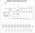
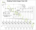
Attached is an updated version of the Alternating Trickle-charger/Timer.
I haven't time to explain it now but essentially it allows for a longer trickle charge, say 70min, the off briefly, then onto the next battery for 70min and so on. I was waiting for parts so I got to playing around with what I think will be a better approach. Each battery will have about 2hrs & 20min of charge/24hrs.

Brian
 

Attachments

SgtWookie

Joined Jul 17, 2007
22,230
You have Carry Out (pin 12) connected to Reset (pin 15).
This will cause your 4017 to be constantly reset; B1 will be high forever.

Don't use the Carry Out for anything.

Attach a 1uF cap from the Reset pin to your V+.
Attach a 100k resistor from the Reset pin to GND.
Attach a 1N4148 or 1N914 diode's cathode to the Reset pin, the anode to GND.
That way, when you first power the circuit up, Reset is pulled high until the 1uF cap is discharged through the 100k resistor, permitting normal counting to commence.
When power is turned off, the 1uF cap is discharged rapidly through the 1N4148/1N914 diode.

You do not show any decoupling caps in your V+ line.
I suggest a 100uF cap centrally located, and a 0.1uF decoupling cap at each IC.

[eta]
I don't know what you're doing with the 4541 and the 2N2222 with all those caps - did you pull that circuit from a datasheet somewhere?
 
Last edited:

Thread Starter

iONic

Joined Nov 16, 2007
1,662
You have Carry Out (pin 12) connected to Reset (pin 15).
This will cause your 4017 to be constantly reset; B1 will be high forever.

Don't use the Carry Out for anything.

Attach a 1uF cap from the Reset pin to your V+.
Attach a 100k resistor from the Reset pin to GND.
Attach a 1N4148 or 1N914 diode's cathode to the Reset pin, the anode to GND.
That way, when you first power the circuit up, Reset is pulled high until the 1uF cap is discharged through the 100k resistor, permitting normal counting to commence.
When power is turned off, the 1uF cap is discharged rapidly through the 1N4148/1N914 diode.
Done...

You do not show any decoupling caps in your V+ line.
I suggest a 100uF cap centrally located, and a 0.1uF decoupling cap at each IC.
I need to understamd the concept of decoupling. I'll search this site or google...

[eta]
I don't know what you're doing with the 4541 and the 2N2222 with all those caps - did you pull that circuit from a datasheet somewhere?
Original circuit can be found here.
 

Thread Starter

iONic

Joined Nov 16, 2007
1,662
Thanks. I found some info from EDN online.

I have re-posted the circuit with some changes. As you have expressed, the pile of Caps and Resistors, and transistor stemming from Pin 5, 6, 7 of the 4541 are mysterious. I had taken it with slight alteration from the link I previously posted. I may not need any of it. I will re-read the 4541 data sheet and try to make sense of it.
 

Attachments

Last edited:

SgtWookie

Joined Jul 17, 2007
22,230
I've never used a 4541 before. I'm quite under the weather this evening, and afraid I'm not up to wading through the datasheet and figuring out what will work. Perhaps in a day or two.
 
Top